USB-1208LS User's Guide Specifications
Digital input/output
Digital type 82C55
Number of I/O 16 (Port A0 through A7, Port B0 through B7
Configuration 2 banks of 8
Pull up/pull-down configuration
All pins pulled up to Vs via 47K resistors (default). Positions available
for pull down to ground. Hardware selectable via zero ohm resistors as a
factory option.
Input high voltage 2.0 V min, 5.5 V absolute max
Input low voltage 0.8 V max, –0.5 V absolute min
Output high voltage (IOH = -2.5 mA) 3.0 V min
Output low voltage (IOL = 2.5 mA) 0.4 V max
External trigger
Parameter Conditions Specification
Trigger source (Note 4) External digital TRIG_IN
Trigger mode Software selectable
Level sensitive: user configurable for
TTL level high or low input.
Trigger latency Burst 25 µs min, 50 µs max
Trigger pulse width Burst 40 µs min
Input high voltage 3.0 V min, 15.0 V absolute max
Input low voltage 0.8 V max
Input leakage current ±1.0 µA
Note 4: TRIG_IN is protected with a 1.5KOhm series resistor.
Counter
Counter type Event counter
Number of channels 1
Input source CTR screw terminal
Input type TTL, rising edge triggered
Resolution 32 bits
Schmidt trigger hysteresis 20 mV to 100 mV
Input leakage current ±1 µA
Maximum input frequency 1 MHz
High pulse width 500 ns min
Low pulse width 500 ns min
Input low voltage 0 V min, 1.0 V max
Input high voltage 4.0 V min, 15.0 V max
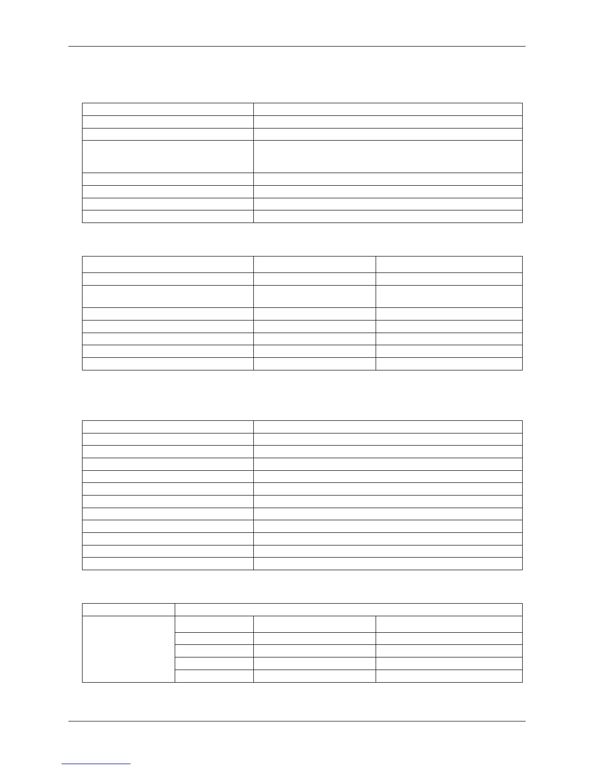
Non-volatile memory
Memory size 8192 bytes
Address Range Access Description
0x0000 – 0x17FF Read/Write A/D data (4K samples)
0x1800 – 0x1EFF Read/Write User data area
0x1F00 – 0x1FEF Read/Write Calibration data
Memory configuration
0x1FF0 – 0x1FFF Read/Write System data
4-3