USB-1608G User's Guide Functional Details
12
An example of a 4-element list is shown in the table below.
Sample channel-gain queue list
Carefully match the gain to the expected voltage range on the associated channel or an over range condition
may occur. Although this condition does not damage the device, it does produce a useless full-scale reading,
and can introduce a long recovery time due to saturation of the input channel.
For more information about analog signal connections
For more information about analog input connections, refer to the Guide to DAQ Signal Connections (available
on our web site at www.mccdaq.com/signals/signals.pdf).
External clock I/O
The device has one external clock input (AICKI) and one external clock output (AICKO) for the analog inputs.
When using an external clock, AICKO outputs the pulse generated from AICKI.
When using the internal clock, AICKO outputs the ADC scan clock.
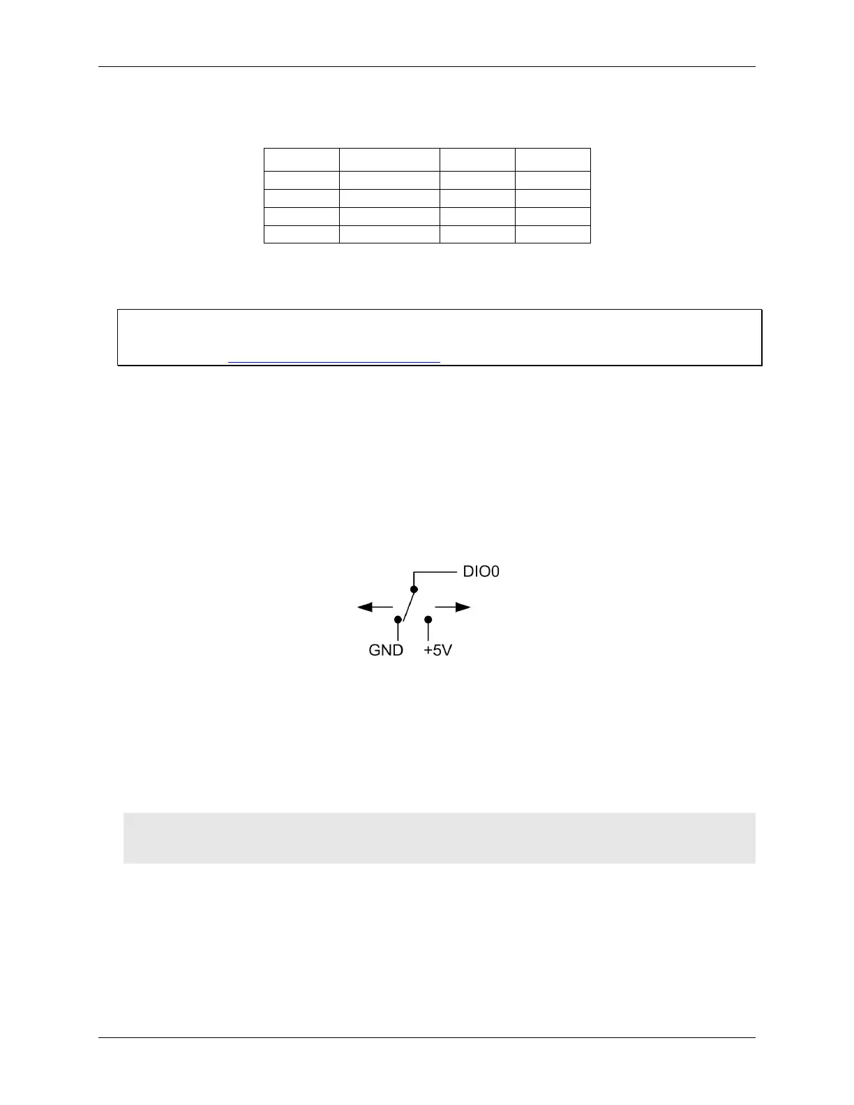
Digital I/O
You can connect up to eight digital I/O lines to DIO0 through DIO7. Each digital channel is individually
configurable for input or output. The digital I/O terminals can detect the state of any TTL-level input. Refer to
the schematic shown in Figure 7.
Figure 7. Schematic showing switch detection by digital channel DIO0
If you set the switch to the +5 V input, DIO0 reads TRUE (1). If you move the switch to GND, DIO0 reads
FALSE (0).
Internal pull-up/down configuration
Unconnected inputs are pulled low by default to 0 V through 47 kΩ resistors via jumper W1 on the circuit
board. The pull-up/pull-down voltage is common to all 47 kΩ resistors. Complete the following steps to
configure these inputs to pull high (+5V).
Caution! The discharge of static electricity can damage some electronic components. Before removing the
device from its housing, ground yourself using a wrist strap or touch the computer chassis or other
grounded object to eliminate any stored static charge.
1. Turn the device over and rest the top of the housing on a flat, stable surface.
2. Peel off the four rubber feet on the bottom of the device to access the screws.
3. Remove the four screws from the bottom of the device.
4. Hold both the top and bottom sections together, turn the device over and rest it on the surface, then
carefully remove the top section of the case to expose the circuit board.