USB-1608G User's Guide Functional Details
13
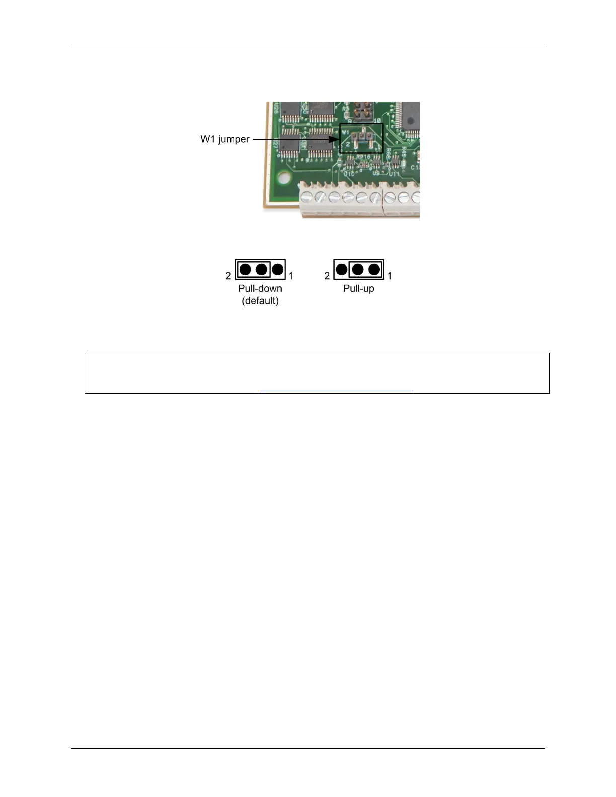
5. Configure jumper W1 for either pull-up or pull-down. The jumper is configured by default for pull-down.
Figure 8 shows the location of the jumper on the board.
Figure 8. W1 jumper location
Figure 9 shows the jumper configured for pull-up and pull-down.
Figure 9. W1 jumper configurations
6. Replace the top section of the case, and fasten it to the bottom section with the four screws. Replace the
rubber feet onto each screw.
For more information about digital signal connections
For general information about digital signal connections and digital I/O techniques, refer to the Guide to Signal
Connections (available on our web site at www.mccdaq.com/signals/signals.pdf).
Trigger input
The TRIG terminal is an external digital trigger input. The trigger mode is software selectable for edge or level
sensitive.
Edge sensitive mode is configurable for rising or falling edge.
Level sensitive mode is configurable for high or low level.
The default setting at power up is edge sensitive, rising edge.
Retrigger mode
Retrigger mode lets you set up repetitive analog input or output trigger events. The trigger is automatically re-
armed after it is activated. Use software to set the A/D or D/A trigger count (the number of samples you want
per trigger).
Counter input
The CTR0 and CTR1 terminals are 32-bit event counters that can accept frequency inputs up to 20 MHz. The
internal counter increments when the TTL levels transition from low to high.