USB-1608G User's Guide Functional Details
9
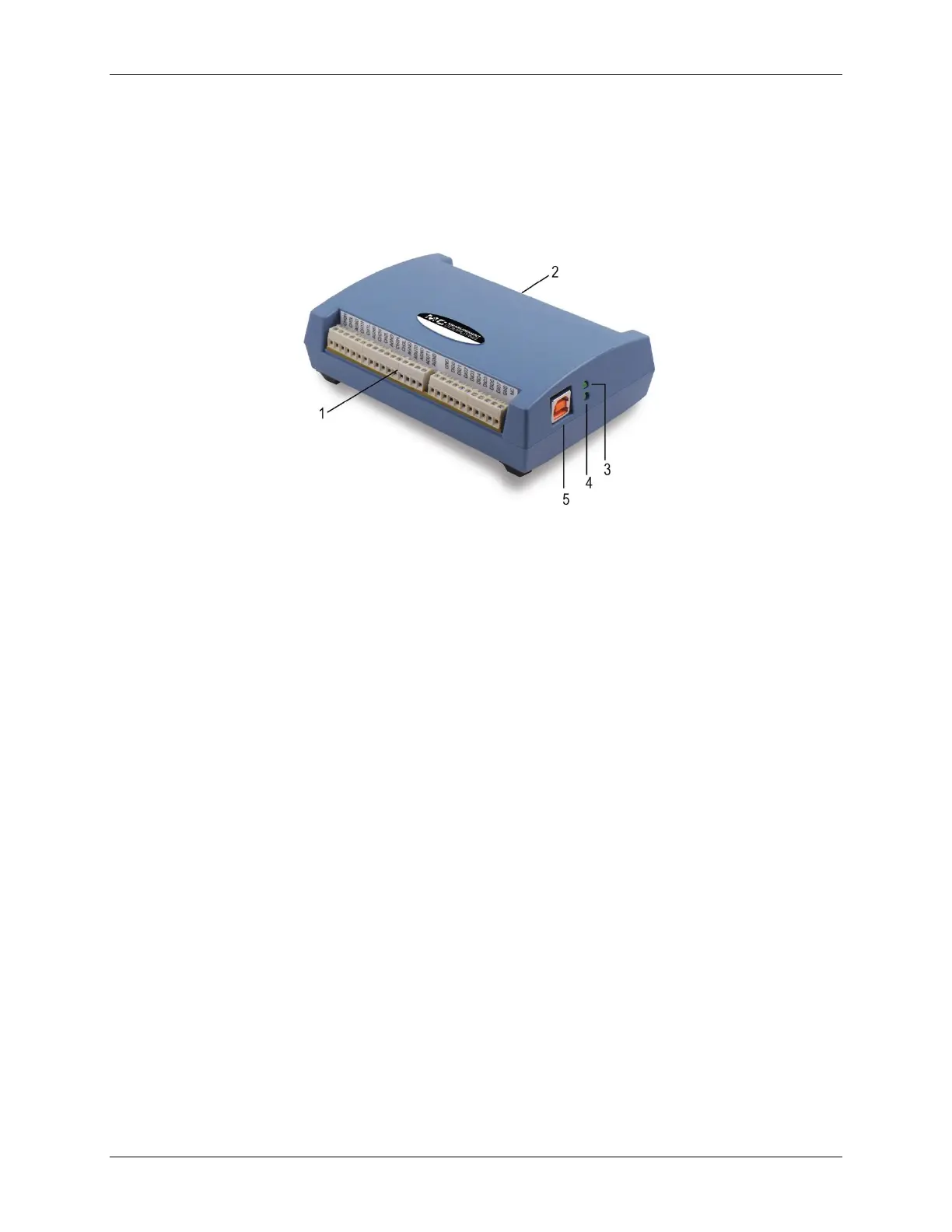
External components
The USB-1608G has the following external components (see Figure 3):
USB connector
LEDs
Screw terminals
Screw terminal pins 1 to 27
Screw terminal pins 28 to 54
Figure 3. External components
USB connector
The USB connector provides +5 V power and communication. No external power supply is required.
LEDs
The USB-1608G has two LEDs – Status and Activity.
The Status LED turns on when the device is detected and installed on the computer.
The Activity LED blinks when data is transferred, and is off otherwise.
Figure 3 shows the location of each LED.
Screw terminals
The screw terminals provide the following connections:
16 SE (CH0 to CH15) or eight DIFF (CH0H/CH0L to CH7H/CH7L) analog inputs
Eight digital I/O bits (DIO0 to DIO7)
One external clock input (AICKI) and one external clock output (AICKO) for analog inputs
One digital trigger input (TRIG)
Two counter inputs (CTR0, CTR1)
One timer output (TMR)
One power output (+5V)
Analog ground (AGND) and digital ground (GND) connections
The single-ended mode pinout is shown in Figure 4, and the differential mode pinout is shown in Figure 5.