16
Chapter 4
Specifications
All specifications are subject to change without notice.
Typical for 25 °C unless otherwise specified.
Specifications in italic text are guaranteed by design.
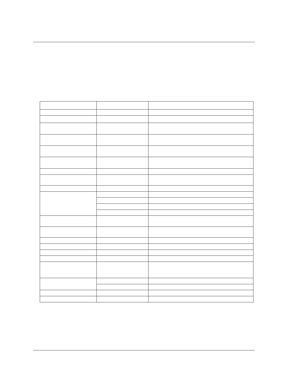
Analog input
Table 1. General analog input specifications
8 differential, 16 single-ended
Software-selectable
±10 V, ±5 V, ±2 V, ±1 V
Software-selectable per channel
Absolute max input voltage
±25 V max (power on)
±15 V max (power off)
1 GΩ (power on)
820 Ω (power off)
All input ranges,
small signal (–3 dB)
Max working voltage (signal
+ common mode)
±10.2 V max relative to AGND
±10.2 V max relative to AGND
±9.5 V max relative to AGND
±9.0 V max relative to AGND
Common mode rejection ratio
(f
IN
= 60 Hz, all input
ranges)
Adjacent differential mode
channels, DC to 100 kHz
0.0149 Hz to 250 kHz; software-selectable
TRIG (see External trigger on page 18)
Internal A/D clock or external A/D clock (AICKI pin)
4 µs
Software-selectable using the internal A/D clock; always
enabled when using the external clock (AICKI pin).
33 to 4000 S/s typ, system dependent
Software-selectable range for each channel