EN
54
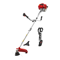
ASSEMBLY
Fitting the shaft
1. Pull out the pin (1) and press in the bottom
part of the shaft (2) so that the pin (1)
clicks in place in the hole (3) in the shaft.
If necessary turn the bottom part of the
shaft (2) backwards and forwards to make
it easier. Check that the pin (1) has gone
completely into the hole.
2. Tighten the knob (4) rmly.
FIG. 2
Fitting the handles
1. Place the left handle (5) and the right
handle (6) in the attachment in the
required position on the shaft. Place the
locking piece (7) and the four screws (8)
over the tubes.
FIG. 3
2. Tighten the screws so that the locking piece
holds both parts of the handle.
FIG. 4
3. The angle of the handle can be changed by
undoing the screws that hold the locking
piece. Tighten the screws again after
adjusting.
FIG. 5
Fitting the safety guard
Fit the guard on its attachment with 4 screws
(3). Tighten the screws rmly with a screwdriver.
FIG. 6
Fitting the trimmer head
1. Align the two holes in the ange and the
guard to each other.
2. Lock the ange with a screwdriver and undo
the nut clockwise with a ring spanner.
FIG. 7
FIG. 8
FIG. 9
3. After removing the nut, release the inner
cap. Lock the ange with a screwdriver, or
equivalent. Place the trimmer head on the
axle. Turn the trimmer head anticlockwise
to lock in place.
4. Remove the trimmer head by locking the
ange with a screwdriver and turning the
trimmer head clockwise to release it.
FIG. 10
Fitting the clearing blade
1. Undo the nut and remove the outer ange.
Fit the blade, the outer ange, the cap and
the nut. Make sure to t the blade with
the direction of rotation specied on the
machine.
2. Lock the ange with a screwdriver and
rmly tighten the nut anticlockwise.
3. Remove the clearing blade by locking the
ange with a screwdriver, locking the nut
with a ring spanner, and taking o the
blade.
FIG. 11
WARNING!
Always check before use that the trimmer head
or clearing blade is correctly tted.
Fitting the strap
Fit the strap as shown in the diagram and adjust
to make it comfortable.