12
General Installation
Pipe Fittings
All pipe connections to the MEGAFLO Eco are made via 22mm compression fittings directly to the unit (nuts and olives supplied). The fittings are
also threaded
3
/
4
” BSP male parallel should threaded pipe connections be required.
Cold Water Supply
A 22mm cold water supply is recommended, however, if a 15mm (
1
/
2
”) supply exists which provides sufficient flow (see section1, p.6 “Water
Supply”) this may be used. More flow noise may be experienced from small bore pipes due to the increased water velocity through them.
The Cold Water Inlet Control kit supplied with the MEGAFLO Eco incorporates a full flow isolating valve which will enable the MEGAFLO Eco to be
isolated from the mains supply for maintenance or servicing. To close the valve the blue handle should be turned so that it lies at 90º to the direction
of flow. To open, turn the handle so that it lies parallel to the direction of flow.
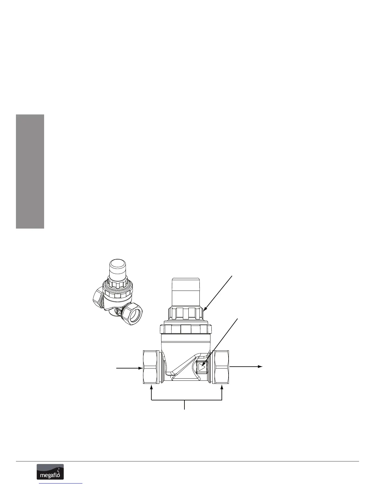
3 Bar Pressure Reducing Valve (see Figure 4 below)
The 3 bar Pressure Reducing Valve can be connected anywhere on the cold water mains supply prior to the MEGAFLO Eco unit. There is no
requirement to site it close to the unit, it can be located at a point where the mains supply enters the premises if this is more convenient but you
must install a non-return valve just after the reducing valve for ease of maintenance.
The 3 bar Pressure Reducing Valve can be installed as a complete one-piece unit or incorporating the stopcock (see Figure 6, p.13). The valve
incorporates a factory set, non-adjustable Pressure Reducer and Strainer and a single Check Valve. The valve can be fitted in any orientation to
suit the installation, however, ensure that the valve is installed with the direction of flow arrows (stamped on the side of the brass body) pointing
towards the MEGAFLO Eco heater.
If a balanced pressure cold water supply is required to a thermostatic shower mixer valve this may be teed off the supply to the MEGAFLO Eco
immediately after the 3 bar Pressure Reducing Valve (see Figure 7, p. 14).
Figure 4 - 3 bar Pressure Reducing Valve
INSTALLATION AND
COMMISSIONING INSTRUCTIONS (2)


 To Next Page