20
L
N
1 2 3
Control Housing Details
Element Connections
1.5mm² 3 Core
HOFR sheathed
cable
Indirect control
wiring
Unvented Hot Water Cylinder
INSTALLATION AND
COMMISSIONING INSTRUCTIONS (2)
Wiring
All electrical wiring should be carried out by a competent electrician and be in accordance with the latest I.E.E. wiring regulations.
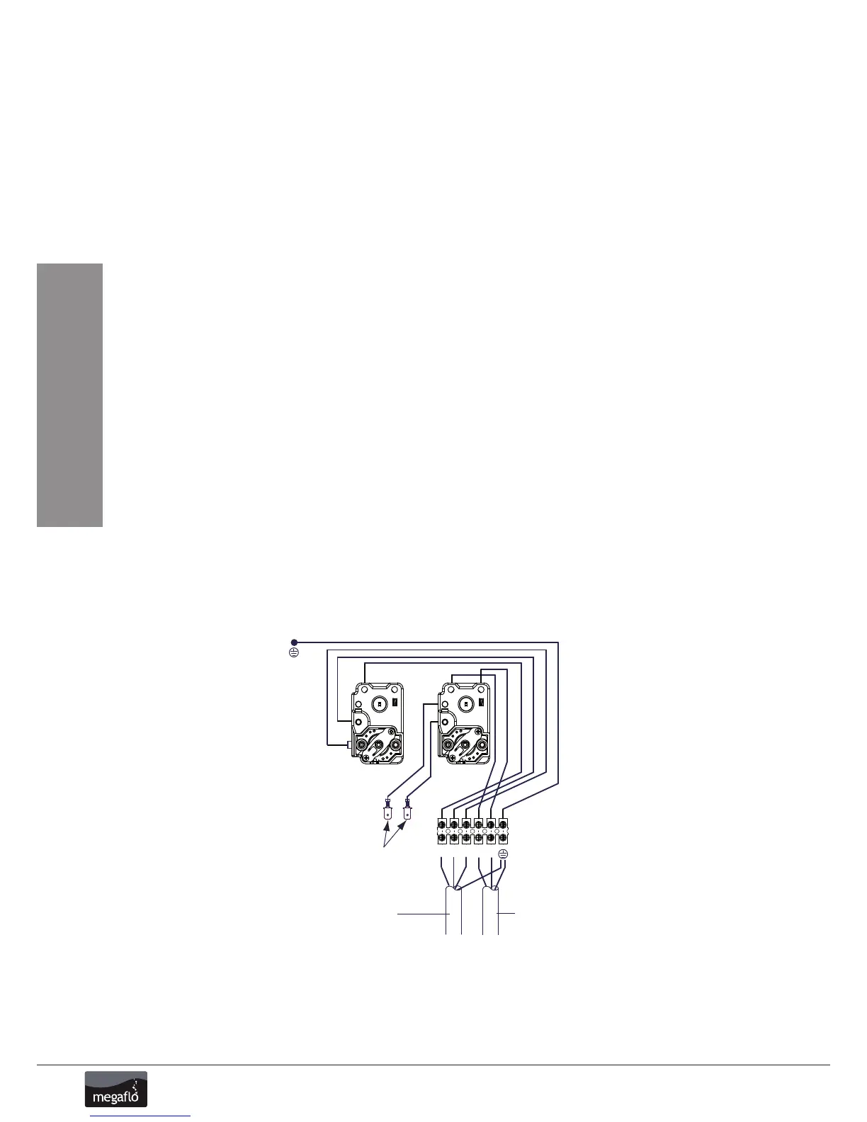
The MEGAFLO Eco indirect combined thermostat and thermal cut-out are factory pre-wired. The 2-port motorised valve supplied MUST be wired in series
with the indirect controls such that the power supply to the valve is interuppted should eithet the thermostat or thermal cut-out operate. Figures 13 and
14, (p. 21) detail the wiring between these controls and the motorised valve. Wiring to external controls is made via the terminal block fitted. The cable
should be routed through the aperture in the terminal cover and secured using the cable grip provided. The indirect thermal cut-out MUST NOT be
bypassed.
Heating System Controls
The controls provided with the MEGAFLO Eco will ensure the safe operation of the MEGAFLO Eco within a central heating system. Other controls will be
necessary to control the space heating requirements and times that the system is required to function. Depending on the boiler selected, heating circuit
design and controls used, it may be beneficial to incorporate a system bypass in the heating system pipework.
The MEGAFLO Eco is compatible with most heatig controls, examples of electrical circuits are given in Figures 13 and 14, (p. 21). However, other systems
may be suitable, refer to controls manufacturers’ instructions supplied with the controls selected, for alternative system wiring schemes.
Immersion heater(s)
The MEGAFLO Eco indirect units are supplied with an immersion heater which can be used as an alternative heat source should the boiler supply need to
be isolated from the MEGAFLO Eco unit.The immersion heater is located within the controls housing, refer to, sections “Wiring and Operation”(see p. 22)
for details of wiring and operation of the immersion heater. 210 litre models and above are supplied with a second blanked off boss which can be used
for the connection of a second immersion heater should this be required.
To remove the blanking plug:
Ensure the cylinder is drained of water. Open the cover to the upper immersion heater boss. Unscrew the backnut using the key spanner provided with the
unit. Remove the blanking plug and sealing gasket from the boss.
Fitting additional immersion heater:
Insert the immersion heater and sealing gasket into the upper boss. Ensure that the sealing gasket is not displaced when inserting. It may be helpful
to support the immersion heater using a round shafted screwdriver inserted into one of the thermostat pockets.Hand tighten the backnut. Secure the
immersion heater in position by tightening with the key spanner provided. If an additional immersion heater and thermostat assembly is required, order
part no. 95:970:554.
Figure 12- Indirect wiring layout


 To Next Page