M
AVTMTTR100-ENG Rev 6 Nov 2015
24
T-Type Transformers
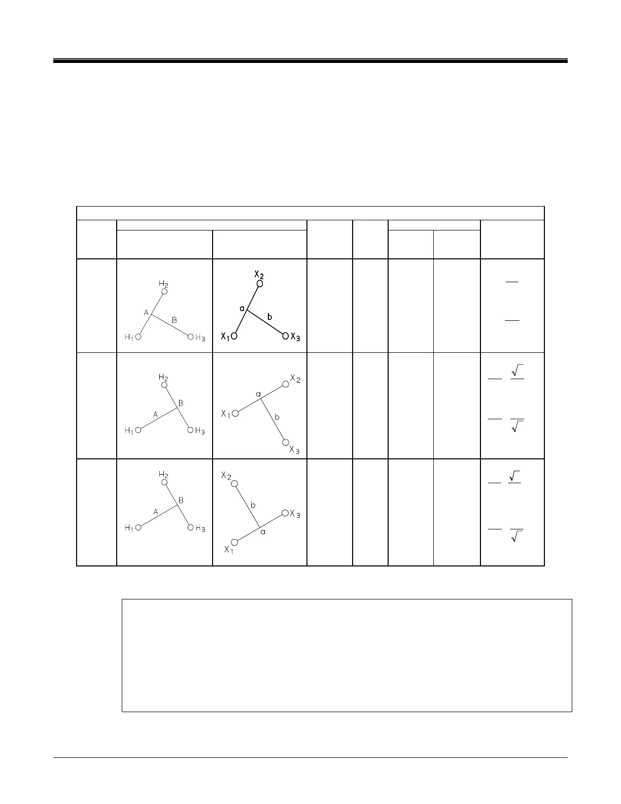
T-type transformers represent a special type of three-phase transformers. This
transformer may be tested as a single phase transformer.
To make a measurement on a T-type transformer, match the vector diagram from
the transformer nameplate to the corresponding winding connection diagram
from Table 5-3 then, select the corresponding IEC vector group (column 1 of
table) on the appropriate setup menu of the instrument.
Table 5-1. ANSI Transformer Winding Phase Relationship
Winding Connection Winding Tested
IEC
Vector
Group
High-Voltage
Winding (H)
Low-Voltage
Winding (X)
External
Jumpers
Phase
tested
High-
Voltage
Winding
Low-
Voltage
Winding
Calculated
Turn Ratio
T-T
0
-
H
1
-H
2
X
1
-X
2
A
B
H
1
- H
2
H
1
– H
3
X
1
- X
2
X
1
– X
3
X
H
V
V
X
H
V
V
T-T
30
lag
H
2
-H
3
X
1
-X
2
A
B
H
1
– H
3
H
2
– H
3
X
1
- X
2
X
1
– X
3
2
3
•
X
H
V
V
3
2
•
X
H
V
V
T-T
30
lead
H
2
-H
3
X
1
–X
3
A
B
H
1
– H
3
H
2
– H
3
X
1
– X
3
X
2
– X
1
2
3
V
V
X
H
•
3
2
•
X
H
V
V
NOTES:
The connection instruction of the TTR100 to the device to be tested is contained
within the TTR100. The connection information is provided as connection guides
and do not suggest the physical location of the
bushings / terminals of the device being tested.
Any connection(s) to ground/case of T-type transformer on H or X side should be
removed before testing a transformer.

 Loading...