Do you have a question about the Megger MIT520/2 and is the answer not in the manual?
Mandatory safety precautions to be observed during the use of the insulation tester.
Emphasizes that the instrument must only be used by suitably trained and competent persons.
Overview of the microprocessor-controlled 5 kV insulation tester and its capabilities.
Details the various features, test modes, and measurement capabilities of the instrument.
Instructions for cleaning the instrument using a damp cloth and mild cleaning agents.
Explains how the instrument is powered and how the internal battery is charged.
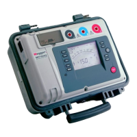
Visual guide to the instrument's buttons, terminals, and LCD display elements.
Operation of the power button and selection of test voltages using ▲ and ▼.
Initiating/terminating tests and toggling between resistance and current displays.
Using Fn for secondary functions and Mode for selecting test types.
Setting test timers and initiating/stopping data recording to internal memory.
Procedures for transferring results to a PC and clearing stored data.
Connecting to PC via RS232/USB and understanding indicator lights.
Description of main test terminals and the function of the guard terminal for leakage reduction.
Details for PC connection and interpretation of the battery level indicator.
Explanation of voltage, timer indicators, and digital display functions.
Functionality of the analogue meter simulation and secondary display for time-based tests.
Table detailing key functions and their actions during pre-test and test phases.
Details on IR test operation, including breakdown, burn, and alarm limit modes.
Explanation of the SV test principle, voltage stepping, and measurement process.
How PI and DAR are calculated and displayed, related to time-resistance measurements.
Description of the DD test for assessing insulation ageing, deterioration, and voids.
Precautions for measuring very high resistances and the role of the guard lead.
Diagram illustrating the internal circuitry and components of the insulation tester.
Comprehensive list of technical specifications including voltage, accuracy, battery life, and ranges.
List of included and optional lead sets, cables, and other accessories for the instrument.
Instructions for returning the instrument for recalibration or repair, including RA number.
Guidance on locating authorized service centres for repairs and maintenance.
The Megger MIT520/2 is a microprocessor-controlled 5 kV digital insulation tester designed for comprehensive insulation resistance measurements and diagnostic tests. It offers a wide range of features for both continuous resistance/current measurement and specialized test modes, with data storage and retrieval capabilities.
The MIT520/2 measures insulation resistance up to 15 TΩ. It can be powered from a mains supply (85-265 Vrms a.c. at 50/60 Hz) or its internal rechargeable battery, which provides at least 6 hours of continuous testing with a 100 MΩ load. The battery level is indicated on the LCD display, and the battery charges automatically when connected to mains, except during testing. An internal battery management system turns the instrument off after ten minutes of inactivity to conserve power. If the battery charge is very low, the instrument will turn off, requiring mains power for use. Recorded test results and settings are retained when the instrument powers off.
The device supports various test modes:
The MIT520/2 offers both 'burn' and 'breakdown' modes for IR tests. In breakdown mode, the test terminates automatically upon insulation breakdown to prevent damage. In burn mode, breakdown detection is disabled, allowing the test voltage to continue, which can help locate the failure point. The instrument emits two long beeps when starting a test in burn mode due to potential damage. An 'Alarm Limit' mode is also available for IR tests, where the instrument beeps if the resistance reading exceeds a user-selectable threshold (10 kΩ to 15 TΩ).
The instrument features an LCD display that shows continuous resistance or current measurements on the main display, with optional resistance, current, or figure of merit measurements (like PI, DAR) on a secondary display. The display also includes a battery bar graph, voltage at terminals, and a timer indicator. An analogue display simulates a meter movement, providing a "feel" for measurement progress.
Controls:
Safety Warnings:
Data Storage and Output:
Guard Terminal: The guard terminal (G) is at the same potential as the negative terminal. It diverts surface leakage currents from the measuring circuit, improving accuracy, especially in cable testing or when moisture/dirt is present. This is particularly useful for measurements above 100 GΩ. The display will show 'FUS' if the internal guard terminal fuse blows.
| Brand | Megger |
|---|---|
| Model | MIT520/2 |
| Category | Test Equipment |
| Language | English |