terminal, or at least 10 kΩ for the negative terminal.
Conversely, if the positive terminal is grounded, then the negative terminal
will be at a voltage equal to the test voltage relative to ground, which will
result in an increase in leakage current, and worsening of measurement
accuracy.
When making measurements above 100 GΩ therefore, the user should
ground the Guard Lead where possible, otherwise parallel leakage paths
may occur.
Alternatively, screened leads are available as an optional accessory from
Megger. The lead to the negative terminal is fully screened. The screen is
plugged into the Guard terminal, diverting any stray leakage currents. This
considerably improves measurements made with a floating output, where
the leads might touch each other or anything other than the test piece.
18
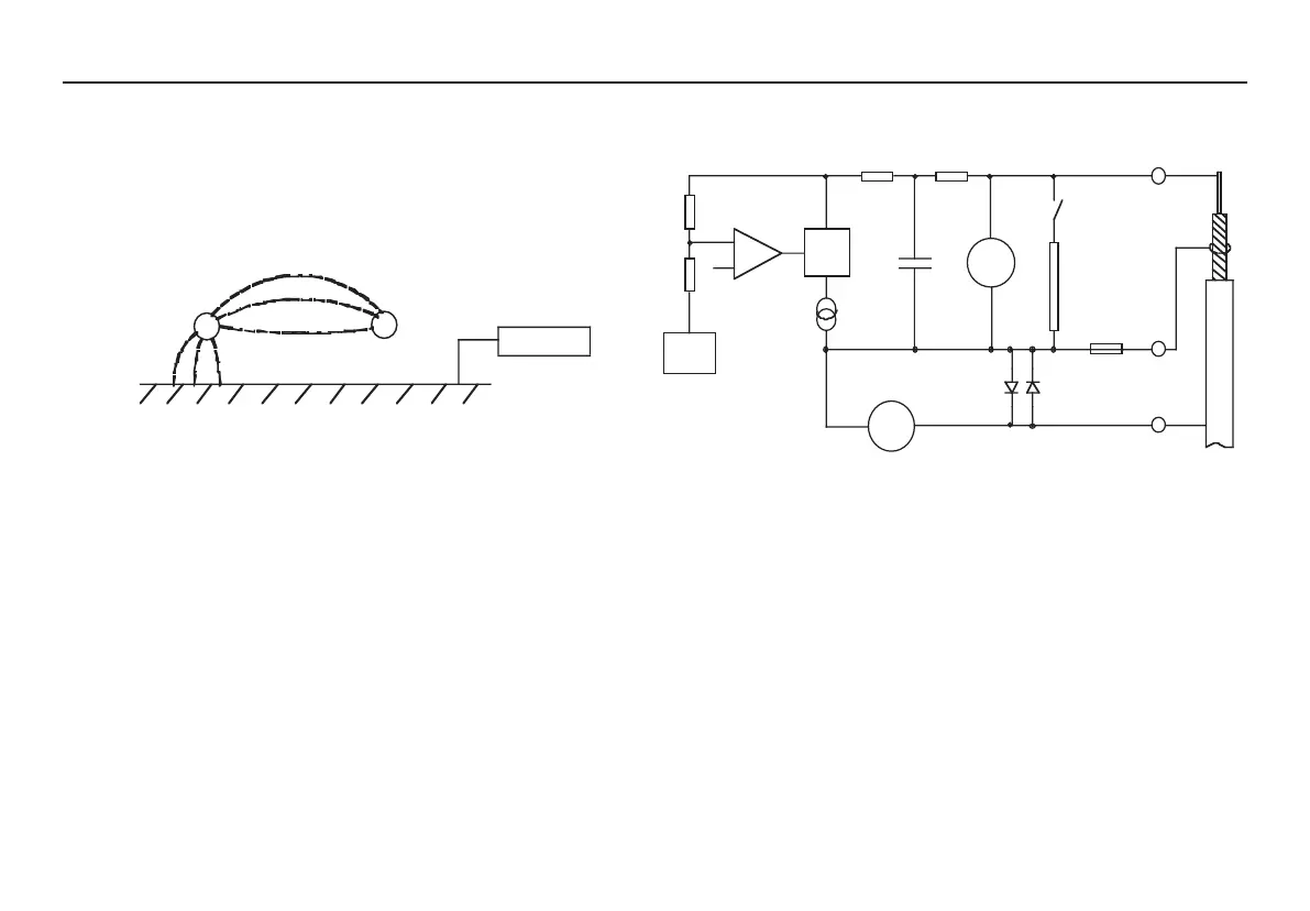
Circuit block diagram
For 5 kV instruments C1 = 47 nF, R1 = 50 kΩ, R2 = 40 kΩ
For 10 kV instruments C1 = 15 nF, R1 = 156 kΩ, R2 = 110 kΩ
+ Test V
0V
Ground
Guard
+
-
100 MΩ
R1
R2
C1
Volts
Fuse
Cable
under
test
+
+
-
-
G
Discharge
resistance
Current
Ref
Voltage
control
Current
Limit
High
voltage
source