Do you have a question about the Megger MIT400/2 and is the answer not in the manual?
Explains symbols marked on the instrument for user instructions, shock risk, and protection ratings.
Details the WEEE Directive regarding product disposal and Megger's registration.
Provides instructions for disposing of batteries according to regulations.
Information regarding important documents to read and keep after unpacking.
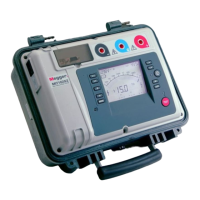
Lists the items included in the instrument's case for various models.
Information on fitting batteries and warnings regarding their cover.
Details functional verification steps for test leads before measurement.
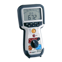
Describes rotary knob and keypad button functions for instrument operation.
Explains the meaning of various symbols and readouts on the instrument display.
Illustrates and describes the input terminals for 2-terminal and 3-terminal configurations.
Guide for connecting test leads to the instrument for 2-terminal measurements.
Details the use of the GUARD terminal for error reduction in specific tests.
Explains how to connect and use 3 terminals for electrical and telecom applications.
Describes how to switch between measurement pairs in 3-terminal operation.
Instructions for using the optional SP5 switched probe for hands-free testing.
Step-by-step guide for measuring AC Trms and DC voltage with 2 terminal instruments.
Procedure for measuring voltage using 2 leads on 3-terminal models.
Details measurements using all three test leads with 3-terminal instruments.
Instructions on how to store measured results for specific instrument models.
Step-by-step guide for performing insulation resistance tests using 2-terminal connections.
Covers buzzer thresholds, ON/OFF control, and PASS/FAIL display for measurements.
Explains Insulation Test LOCK and displaying leakage current.
Details variable voltage testing and PI/DAR test procedures for specific models.
Explains continuity test ranges, test current, and automatic start.
Describes the default single direction test and how to enable bi-directional testing.
Procedure for removing test lead resistance from measurements.
Covers buzzer PASS/FAIL threshold, ON/OFF, and PASS/FAIL limit alarms.
Details the configurable test current options for continuity testing.
Enables silent mode with PASS/FAIL indication and visual cues.
Explains REL mode for relative resistance measurements.
Procedure for measuring capacitance using 2-terminal connections.
Details measuring cable length using capacitance on specific models.
Refers to section 7.3 for 3-terminal capacitance measurement.
Procedure for storing measured results in the instrument's memory.
Instructions on how to recall stored test results from the instrument.
Procedure for deleting single or all stored test results.
Prepares instrument for Bluetooth communication to download results to a PC.
Step-by-step guide for pairing the instrument with a PC using Bluetooth.
Instructions for downloading test results from the instrument to a computer.
Details the process of entering SETUP and configuring various options.
Lists accuracies and ranges for insulation and continuity measurements.
Details specifications for frequency, capacitance, storage, and data download.
Covers power supply, battery life, dimensions, weight, fuse, and safety standards.
Details operating/storage conditions, altitude, and IP rating.
Explains the battery indicator and the procedure for replacing batteries.
Describes the blown fuse indicator and the procedure for fuse replacement.
Guidelines for preventive maintenance, including test lead checks and cleaning.
Covers instrument repair, warranty terms, and calibration services.
| Brand | Megger |
|---|---|
| Model | MIT400/2 |
| Category | Test Equipment |
| Language | English |