14
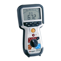
Terminal layout - 3 Terminal instrument:
- Figure 5
3 Terminal connection example:
CAT III 600 V
G
E
T
A
R
B
G
g
B / Ring / Live
E / Ground / Earth
A / Tip / Neutral
- Figure 6
7.3.2 3 terminal operation:
By pressing the A-E-B button on the keypad the active measuring pair on the Instrument changes as per the indication on the display,
as below:
- Figure 7
With each press, the display will change from:
From
to to and back to
- Figure 8
Or, if 'T-G-R' is enabled in setup:
From
to to and back to
For example, in VOLTS mode, the voltages on the A-B pair, the A-E pair or the B-E pair can all be measured without having to
disconnect the test leads from the A, B and E conductors.