26
9.4.2 Using 3 test leads
All three connections can be connected to the circuit under test, for example:
Electrical testing Telecommunications USA Telecommunications EU
A (T) = Neutral T = Tip A = A
B (R) = Live R = Ring B = B
E (G) = Earth E = Earth E = E
The measurement should default to Live - Neutral (B-A) when the instrument is switched on.
Pressing the A-E-B (T-G-R) button will cycle through the voltages on each part of the circuit, see section 7.2.
9.5 ESD testing mode (MIT415/2)
The MIT415/2 can be configured in SETUP to display an analogue arc with 10
4
, 10
5
, 10
6
etc on the analogue arc rather than the kW,
MW, GW.
The mode also enables a PASS/FAIL limit bar, which stops at 10
6
to indicate a PASS threshold without setting a limit alarm.
A limit alarm can also be set in SETUP if required.
9.5.1 Testing in ESD mode
To enable the ESD mode, refer to SETUP section 13.
1. Connect test leads to the RED/BLACK test sockets only.
2. Select one of the INSULATION measurement voltages on the range knob [
MW
] range.
3. Connect the test leads to the appropriate test weights and place the test weights on the surface of the material to be
measured, as per the relevant test standard requirements.
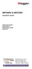
4. Press and hold the test button. The instrument will display the resistance across the test leads as below:
10
10
1010
10
10
9
8
7
6
5
4
W
W
M
V
- Figure 32
Notes:
To LOCK the insulation test ON, see section 9.1.5.
9.5.2 Leakage current display
Whilst the test is running it is possible to display the leakage current rather than the test voltage in the smaller digital readout.
To display the LEAKAGE CURRENT during the test, see section 9.1.6