29
10.2 Single or bi-directional testing
The default setting is for a single direction continuity test. This can be changed to a bi-directional test in SETUP. see section 13.
First test: Red terminal = 4.5Vdc, Black terminal = 0Vdc
Second test: Red terminal = 0Vdc, Black terminal = 4.5Vdc
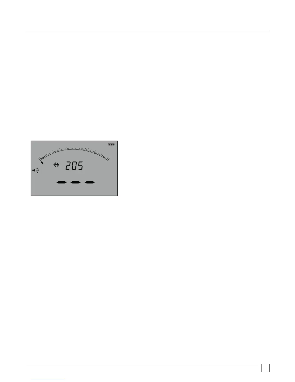
As with the single test, the Bi-directional test the measurement is automatic. The measurement displayed is the higher of the two
directional measurements.
Polarity of the primary result is shown in the display as an arrow:
-> = Forward polarity
<- = reverse polarity
Both the single and bi-polar tests are automatic, starting as soon as the test leads contact the circuit to be tested.
z
k
100 0
8 00
6 004 00
2 00
0
W
W
Am
- Figure 34
10.2.1 Entering bi-directional mode
1. Refer to section 13.1 - SETUP REV=ON
2. Display will show <- and -> as the measurement changes polarity.
NOTE: When enabled, the buzzer will sound and stop the bi-directional test. To resume bi-directional testing, press the buzzer button.
10.3 Test lead NULL
Enabling the lead NULL value
The test lead resistance can be removed from the displayed measurement. This "Null" is restricted to to 9.99 0hms
The "Null" value is retained when an instrument Is switched off.
It is recommended the "Null" value is checked or re-nulled periodically as the resistance of test leads and/or their connections can
change over time or after disconnection and reconnection.
1. Whilst in continuity mode, short the test leads together.
2. When the value settles, press the TEST button. The MIT will subtract the value of the test leads for all future measurements,
until the NULL value has been removed.
The NULL symbol
z will be displayed when the NULL function is active.
Typical test lead values per pair:
Standard unfused 1.2m test leads = 0.05 ohm
10A fused 1.2 m test leads = 0.07 ohm
500mA Fused 1.2m test leads = 1.80 ohms
These are only a guide and can change significantly between manufacturers.