17
other current component, comprising the released absorption current,
decays from a lower value with a relatively long time constant of up to
several minutes. If this component of the discharge current is large (>7 @
500 V test voltage) then the insulation condition is poor.
The main timer will default to 30 minutes, which is normally sufficient
time for full absorption to take place in an insulation material. The default
test voltage is set to 500 V. The ‘DD’ test requires the instrument to
measure the discharge current 1 minute after the removal of the test
voltage. At this time the capacitive current should be insignificant
compared with the released absorption current. On completion of the
test, the instrument uses this measurement along with the test voltage and
calculated capacitance to produce a figure of merit indicating the quality of
the insulation.
Dielectric Discharge (DD) = I
1 min
V x C
where I is the measured current expressed in milliamps (mA), V is the test
voltage in Volts (V), and C is the measured capacitance in Farads (F).
Measurements above 100 GΩ
Measurements up to 100 GΩ can be made without any special precautions,
assuming that the test leads are reasonably clean and dry. The guard lead
can be used to remove the effects of surface leakage if necessary. When
measuring resistances above 100 GΩ, the test leads should not be allowed
to touch each other, or any other object since this will introduce leakage
paths. Sharp points at the test lead connections should also be avoided
since this will encourage corona discharge.
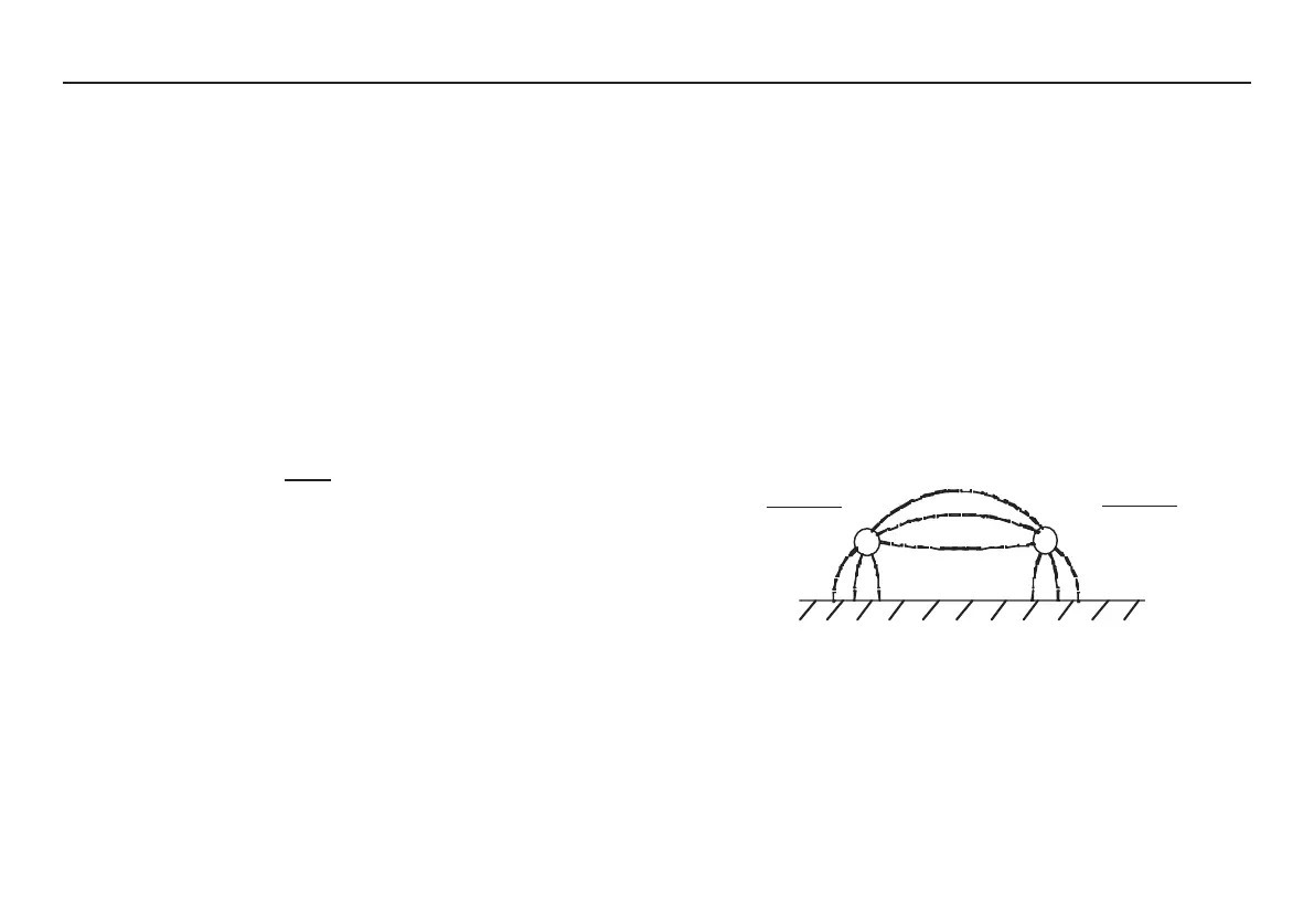
The output is isolated, and so will float relative to ground such that the
positive terminal is at plus half of the test voltage, and the negative
terminal is at minus half of the test voltage with respect to ground.
Leakages therefore occur between the positive terminal and ground,
between the negative terminal and ground, and directly between the
positive and negative terminals. These leakages have a significant effect
and can occur through the air itself.
If the guard lead is connected to ground, then since the negative terminal
is at the same voltage as the guard terminal, the leakage into the negative
terminal will be considerably reduced. This will improve accuracy because
the current flowing into the negative terminal is measured by the
instrument and used to calculate resistance. This technique is only
permissible if the item under test is isolated from ground. “Isolated” in this
context means insulated by a resistance of at least 5 MΩ for the positive
+ Test V
2
- Test V
2
Ground
+
-