3
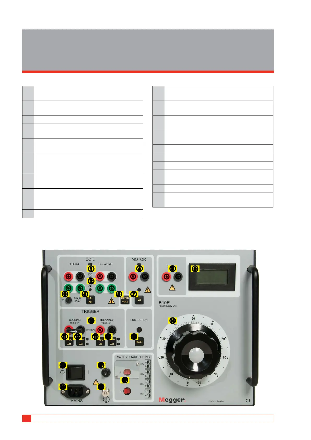
Control panel
1 Output for DC voltage supplied to closing/
breaking coil
2 Output for AC voltage supplied to closing/
breaking coil
3 F2. 4 A fuse for AC outputs
4 Changeover switch used to select either DC or
AC coil outputs
5 Changeover switch used to select either coil
outputs or spring-charging motor outputs
6 DC voltage outputs for spring-charging motor.
Provide unsmoothed, half-wave rectified DC
ranging up to 18 A
7 Button for turning on spring-charging motor
voltage
8 Current shunt output used to measure current,
in coils or spring-charging motors (max 5 A
continuous)
9 Voltmeter
10 Input for external trig signal or short-circuiting
jumper
11 Button for manual trigging pulse via coil out-
puts. (Switch 12 set to voltage position)
12 Changeover switch used to select either con-
tact sensing or voltage sensing at the trig input
13 Reset button for thermal, overload and/or time-
limit cut-outs
14 Variable transformer
15 Master ON/OFF switch
16 Inlet for mains power
17 F1. 7 A miniature circuit breaker for DC spring-
charging motor
18 Grounding terminal
19 Changeover switches (A) and (B) for incoming
power 115/230/135/250 V AC
❻
❼❸
❹ ❺
❽ ➒
❿
➊
⓫ ⓬ ⓭
⓮
⓯
⓰
❷
⓱
⓳
⓲
⓫ ⓬
10 B10E ZP-BG02E BG0140ME
3 CONTROL PANEL