Controls, Indicators, and Connectors
!
AVTMDELTA4000-EN Rev 6 April 2018
17
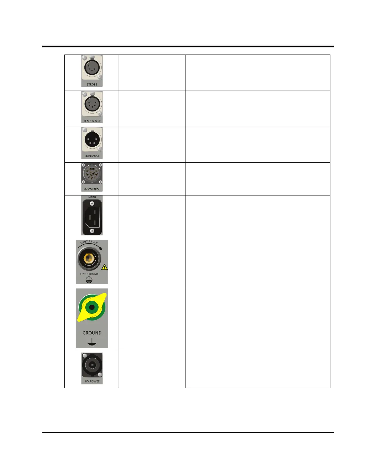
Receptacle for connecting the warning strobe
light
Receptacle for connecting the temp and humidity
sensor (optional accessory)
Receptacle for connecting the test set to an
optional Resonating Inductor (Cat. No. 670600-
1) for extended capacitance range.
Receptacle for the control cable between the
control and HV units
Receptacle for connecting the test set to an AC
power source as marked on panel.
Receptacle for connecting the test ground cable
between the test set and ground (normally station
ground) near the test object
This wing nut is for connecting an additional
safety ground between the control and HV units
or to ground external objects e.g. optional trolley
Receptacle for the power cable between the
control and HV units
 Loading...