12
and the solution may be to wait until the interference
has subsided. Alternatively, choose a new position for
the two remote test spikes, by re-siting them at right
angles to their first position; still in a straight line, and
try again.
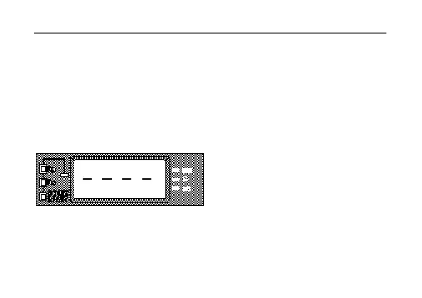
REVERSE POLARITY
When the Potential leads are reversed with respect to
the Current leads, the display flashes between the test
bars and a reading. To take a valid reading, ensure that
the ‘P1’ electrode is closer to ‘C1’ than the ‘P2’
electrode.
Fig. 6 Reverse Polarity Indication
SETTING UP THE TEST SPIKES ETC.
For earth electrode testing and for earth resistivity
surveying, the instrument’s test leads are connected to
spikes inserted in the ground. The way the connections
are made depends on the type of test being undertaken
and the details are given in the next section,
‘
Measuring Techniques’.
Test spikes and long test leads are necessary for all
types of earth testing and the optional earth testing field
accessory kits contain the basic equipment.
OPERATION