28
The
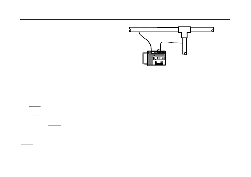
DET 5/4 will measure metallic resistances of low
inductance or capacitance. To test the continuity of
conduit or other earth conductors the instrument can
be connected as a 4 pole tester, or connected as
shown in Fig. 20. Ensure that the circuit is de-
energised, before connecting the instrument for
measurement.
Note:- Due to the inherent high accuracy of the
instrument and the low continuity resistance to be
measured, contact resistance between the test lead
clips and the conduit becomes a factor in the measured
value. Contact resistance should therefore be kept as
low as possible.
1) Using a shorting bar supplied, short together
terminals ‘
P2’ and ‘C2’.
2) Firmly
connect a test lead to ‘C1’,and the other
test lead to ‘
P2’ and ‘C2’.
3) Firmly
connect the free ends of the test leads
across the isolated circuit under test.
4) Press the
3 pole test push, and take a reading in
the normal way.
The resistance of the two test leads can be found by
firmly joining their free ends together, pressing the
3 pole test push and taking the reading in the usual
way. Test lead resistance can then be subtracted from
the original reading, to give a ‘true’ value of continuity
resistance.
Fig. 20 Continuity testing.
MEASURING TECHNIQUES Continuity Testing
k
C1
P2
C2
E
SH
4
POLE3 POLE
MEASURE R
E
P1
ES
MEGGERMEGGER
®
DET5/4DDET5/4D
EARTHEARTH
TESTERTESTER