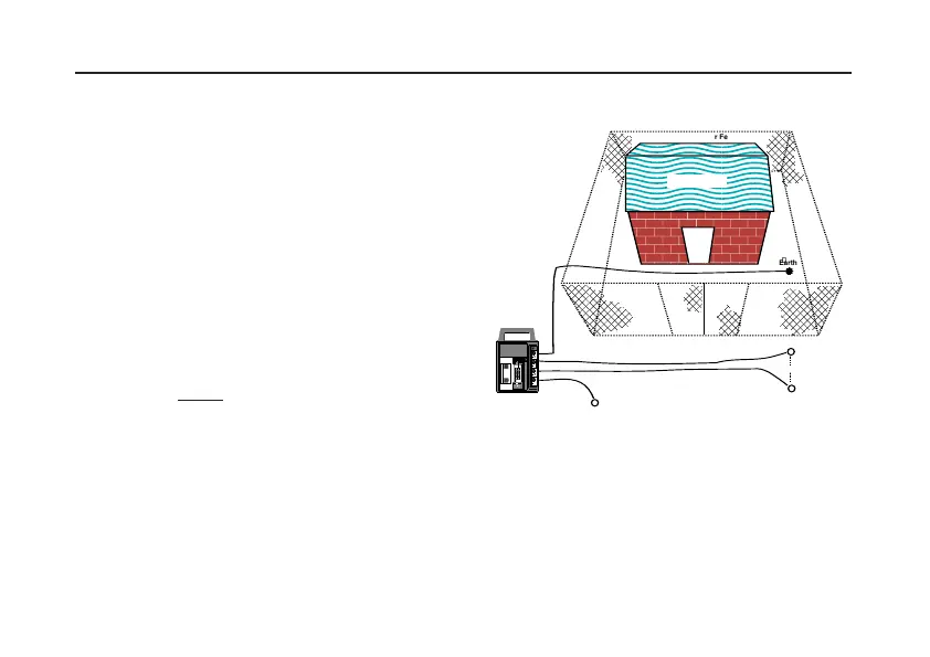
DETERMINING ‘STEP’ POTENTIAL
‘Step’ potential is the potential difference a person
would experience between his feet as he walked
across the ground in which a fault current was flowing.
Firmly connect the instrument as follows :-
1) Terminal '
C1' to the substation earth.
2) Terminal '
C2' to the Current spike inserted in the
ground some distance away.
3) Firmly connect the '
P1' and 'P2' terminals to test
spikes inserted in the ground 1 metre apart, (or the
length of a step) at positions
A and B respectively.
A is nearest to the substation earth.
4) Press the
4 pole test push, and take a reading in
the normal way.
Record the resistance indicated. This is the effective
resistance across the positions
A and B, as seen by
the test current.
The maximum value of the current that would flow in
the earth when a fault to earth occurred at the
substation must again be known. From Ohm's Law the
‘Step potential’ can be calculated.
Fig.17 Determining ‘Step’ potential
24
MEASURING TECHNIQUES Testing Earth Electrodes
k
C1
P2
C2
E S H
4 POLE3 POLE
MEASURE R
E
P1
ES
MEGGERMEGGER
®
DET5/4DDET5/4D
EARTHEARTH
TESTERTESTER
Earthed Perimeter Fence
1m
A
B
SUBSTATION