www.megger.com
t
14
Operating Principle
Figure 5:
NOTE : Switching sensitivity between Level 1 and Level 3 increases the sensitivity by a factor of 5.
Maximum tracing depth 2.0 m.
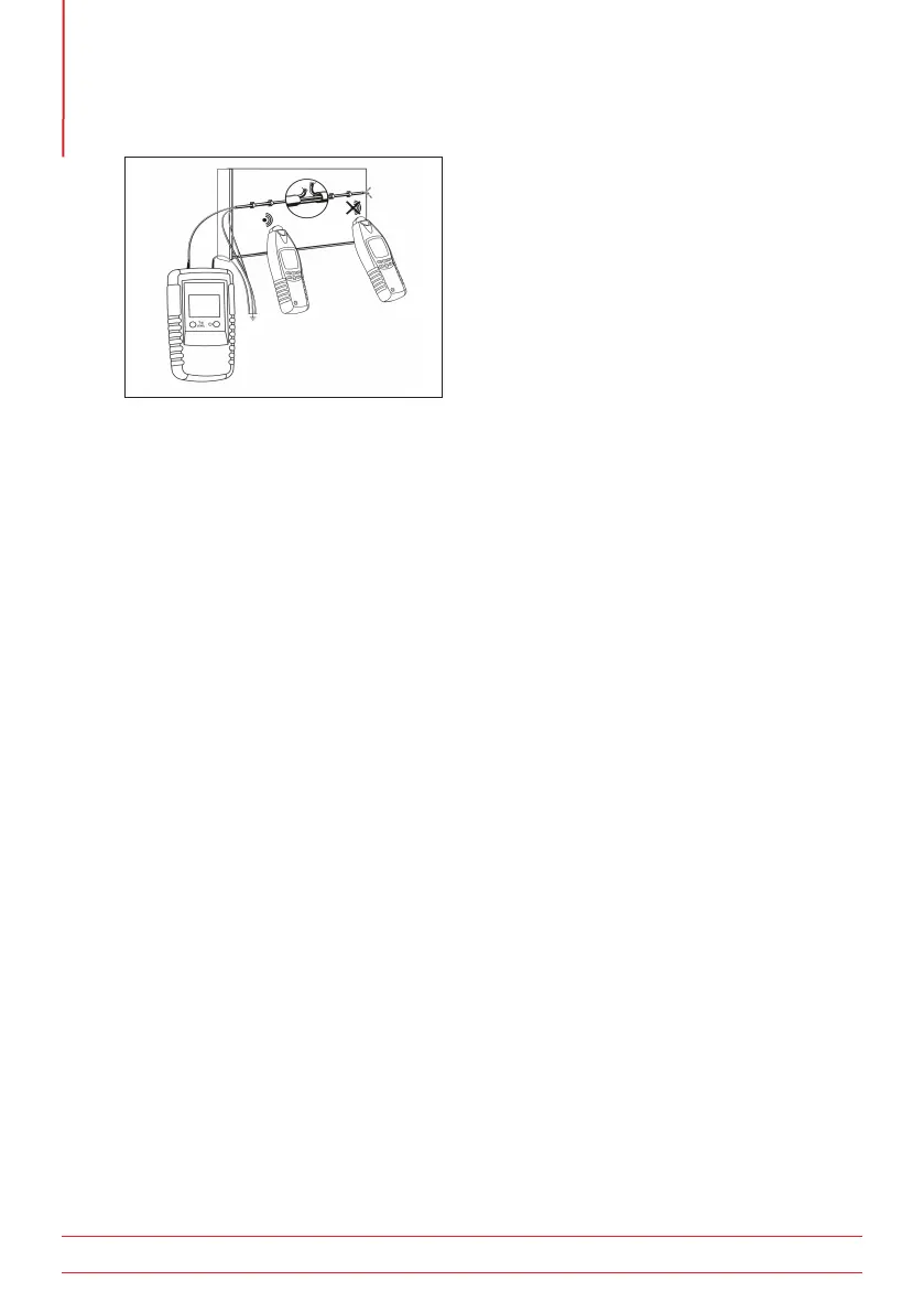
5.6 Locating of line interruptions using two transmitters (single-pole method)
When locating a interruption using a single transmitter from one end of the conductor, precise location
may not be possible in the event of field disturbance on a cable. This can be overcome by using a second
transmitter (available separately) connected to the other end of the cable. In this senario, each transmitter is
set to a different transmission code (e.g. Code 1 and Code 2).
If the two transmitters are connected as shown in Figure 6, the receiver will indicate “1” to the left of the
interruptions; and “2” on the right. As the receiver reaches the interruption, no line code will be displayed
due to the overlapping of the two transmitter signals.
5.6.1 Requirements:
The circuit under test must be isolated (dead).
All cables not being used must be connected to earth, as shown.
Both transmitters must be connected exactly as shown.
The interruption is shown at the point the receiver has no transmitter code visible.
The earthed connections must be connected to a known earth, either on an existing circuit or any earthed
metalwork such as a water pipe.
Make sure during interruption locating in multi-wire shielded conductors and cables, that all remaining
cables are connected to earth. This is required to avoid inductive disturbance. (Figure 6)

 Loading...