www.megger.com t
15
Operating Principle
Figure 6:
The tracing depth of sheathed cables and conductors is different due to the individual cores being twisted
around each other. To pin-point an interruption, a resistance greater that 100 kΩ must be present.
Verification of the resistance can be made using a simple multimeter.
NOTE : Switching sensitivity between Level 1 and Level 3 increases the sensitivity by a factor of 5.
Setup: manual mode, minimal sensitivity. Maximum tracing depth 2.0 m.
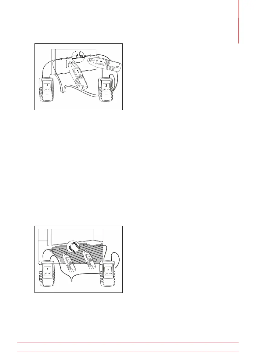
5.7 Error detection in electrical under-floor heating (single-pole method)
The connection conditions:
If a shield mat or shield wiring is located above the heating cables, no earth connection may exist. If
required, separate the shield from the earth connection.
Switching sensitivity between Level 1 and Level 3 increases the sensitivity by a factor of 5.
A second transmitter is required for this application. (Figure 7)
Setup: manual mode, minimal sensitivity. Maximum tracing depth 2.0 m.
Figure 7:
5.8 Locating of bottlenecks (obstructions) in installation pipes (single-pole method)
When locating of bottlenecks in installation pipes, All circuits in the pipe must be dead, isolated and earthed.
Connect transmitter to the metal coil and auxiliary earth as shown in figure 8.

 Loading...