www.megger.com
t
16
Operating Principle
Figure 8:
NOTE : If you only have a non-conducting coil it is recommended you slide a cable up to the
obstruction in the pipework.
NOTE : Switching sensitivity between Level 1 and Level 3 increases the sensitivity by a factor of 5.
Setup: manual mode, minimal sensitivity. Maximum tracing depth 2.0 m.
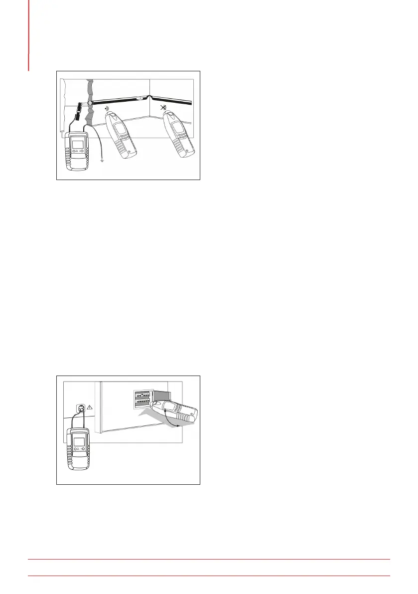
5.9 Fuse Location (double-pole method)
WARNING : Care must be taken when making any connection to live or potentially live circuits.
Correct safety procedures must be followed.
Connect the “red” transmitter terminal to the line conductor and the “black” terminal to the neutral
conductor of the circuit. Ensure the transmitter is set on level one (single bar).
Precise fuse location within the distribution board will depend upon the condition and routing of the wiring.
By setting the transmitter at level one (single bar-graph) the possibility of induced signals in other circuits is
reduced. If safe to do so, the board cover can be removed to allow exact cable identification made at the
fuse termination (figure 9).
Figure 9:
NOTE : Set transmitter to LEVEL I
NOTE : Switching sensitivity between Level 1 and Level 3 increases the sensitivity by a factor of 5.