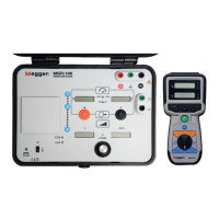
The Megger MGFL100 is a ground fault locator designed to identify ground faults in various electrical systems. It consists of a transmitter and a receiver unit, along with several accessories, to facilitate fault location.
Function Description:
The primary function of the MGFL100 is to locate ground faults up to 400 kΩ on online ungrounded DC systems. With the optional AC Filter, it can also locate ground faults up to 400 kΩ on online IT grounded AC systems. Additionally, the receiver can trace 60 Hz and 50 Hz currents on TT grounded systems with ground faults. The transmitter injects a fault current into the system, and the receiver, equipped with a current clamp, measures this current to pinpoint the fault location.
Important Technical Specifications:
Transmitter:
- Working Voltage: 600 VDC max using fused test leads.
- Output Voltage Range: 0.0 to 50.0 V RMS.
- Output Frequency: 5.12 Hz.
- Output Current: 0 to 160 mA RMS.
- Output Power: 5 Watts.
- Display: LCD, TN, Positive, Reflective, 0.4" high digits, Seven segment with decimal points, 3.5 digits.
- DC Voltage Measurement Range: 0.0 VDC to 600 VDC.
- Accuracy: ±5% of reading ± 2 Least Significant Digits.
- Speed of Measurement: < 3 seconds.
- Display Resolution: 0.0 VDC to 199.9 VDC / 200 VDC to 600 VDC Auto-ranging.
- Resistance Measurement Range: 0.0 kΩ to 400 kΩ.
- Resolution: 0.1 kΩ (< 175.0 kΩ), 1 kΩ (> 199.9 kΩ).
- Accuracy: (±10 ± 280 x RC) % ± 1 Least Significant Digit.
- Speed of Measurement: < 3 seconds.
- Display Resolution: 0.0 kΩ to 199.9 kΩ / 199.9 kΩ to 400 kΩ Auto-ranging.
- Capacitance Measurement Range: 0.00 µF to 19.99 µF.
- Resolution: 0.01 µF.
- Accuracy: ±20% ± (.0027 / R) Fd ± 1 Least Significant Digit.
- Speed of Measurement: < 3 seconds.
- AC Voltage Measurement Range: 0.0 V RMS to 50.0 V RMS.
- Resolution: 0.1 V RMS.
- Accuracy: ±5% of reading ± 2 Least Significant Digit.
- Speed of Measurement: < 3 seconds.
- AC Current Measurement Range: 0.0 mA RMS to 160 mA RMS.
- Resolution: 0.1 mA RMS.
- Accuracy: ±5% of display ± 2 Least Significant Digit.
- Response time: < 3 seconds.
- Voltage limit: Password protected programmable from 0 to 50V.
- Current limit: Password protected programmable from 0 to 160mA.
- Battery Type: Four Li-Ion Protected Cells (18650).
- Run Through Time: Up to 4 hours.
- Charge Time: < 8 hours.
- Battery Status Indication: LED, Red / Amber / Green.
- Size: 36.1 x 30.5 x 19.5 cm (14.2" x 12.0" x 7.65").
- Weight: 6.00 kg (13.2 lbs) (with batteries installed).
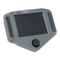
Receiver:
- Visual Alarm Range: Selectable - 30%/40%/50%/60%/70% of reference.
- Audio Alarm Range: Selectable - 30%/40%/50%/60%/70% of reference.
- Receiver Filter Range: Selectable 5.12Hz or 50/60Hz.
- Display: LCD, TN, Positive, Reflective, 0.4" high digits, Seven segment with decimal points, 3.5 digits.
- Resistive Current Measurement Range: 0.00 mA to 160 mA.
- Resolution: 0.01 mA (< 19.99 mA), 0.1 mA (> 19.99 mA).
- Accuracy: ±5% of reading ± 0.01 x IC ± 2 Least Significant Digits.
- Speed of Measurement: < 3 seconds.
- Capacitive Current Measurement Range: 0.00 mA to 160 mA.
- Resolution: 0.01 mA (< 17.50 mA), 0.1 mA (> 19.99 mA).
- Accuracy: ±5% of reading ± 0.01 x IR ± 2 Least Significant Digit.
- Speed of Measurement: < 3 seconds.
- Battery Type: Six AA alkaline cells.
- AC Power Adapter: 90 to 264Vac 47 - 63Hz.
- Run Through Time: Up to 4 hours.
- Battery Status Indication: Visual: LED, Red / Amber / Green.
- Size: 22.1 x 10.4 x 5.1 cm (8.7″ x 4.1" x 2.0").
- Weight: 1.00 kg (2.2 lbs) (with batteries installed).
Environmental:
- Operating Temperature: -10°C to +50°C.
- Storage Temperature: -20°C to 60°C.
- Humidity: 95% Relative Humidity, Non-Condensing.
- IP Rating: 51 when closed.
Safety:
- Insulation: IEC61010.
- CAT Rating: IV @ 600V.
Usage Features:
Transmitter:
- Battery String Connections: Red to positive, green to earth ground, black to negative.
- Safety Earth Connection: For connecting to earth ground.
- Capacitive Sync Connection: For connecting the sync cable.
- Positive Output ON/OFF Button: To initiate current injection from the positive side.
- Negative Output ON/OFF Button: To initiate current injection from the negative side.
- Voltage Output Adjust Knob: To adjust the output voltage.
- Displays: Separate displays for positive voltage/resistance, negative voltage/capacitance, voltage output, and current output.
- Power ON/OFF Button: To power the unit.
- Setting Voltage and Current Limits: Password-protected programmable limits for voltage (0-50V) and current (0-160mA). This is done by holding the "+" and "-" buttons while powering on the transmitter and entering a password.
Receiver:
- CT Inputs: For connecting the current clamp.
- SYNCH Input: For connecting the sync cable.
- Battery Test Button: To check receiver battery status.
- Power On/Off Button: To power the unit.
- Function Button: To deactivate the low pass filter for tracing 50/60Hz current.
- Alarm Knob: Selects alarm level (30%, 40%, 50%, 60%, 70% of reference) and audio/visual alarm.
- Save Button: To save displayed values (total current, resistive current, reactive current).
- Recall Button: To recall saved values.
- IT Indicator: Lights when the displayed value is total current.
- Alarm Indicator: Lights when the receiver locates the circuit with the fault.
- Save LED: Lights during save operation.
- Displays: Top display for total or fault current, bottom display for reactive current.
Fault Location Procedures:
- Ungrounded DC Systems:
- Verify transmitter and receiver batteries.
- Connect the green safety earth cable from the transmitter to earth.
- Connect the black terminal to the negative side of the battery string and the red terminal to the positive side.
- Turn on the transmitter and identify the faulted side by viewing positive and negative voltages.
- Press the appropriate output button (+ or -) and adjust voltage to 10V (or 10-25mA if low impedance fault).
- Note resistive and capacitive readings.
- Connect the current clamp to the receiver and place it around the output lead.
- Connect the sync cable between the receiver and transmitter.
- Note total current, resistive current (fault current), and reactive current. Save these values.
- Set the receiver alarm level (e.g., 50%).
- Trace the fault by placing the CT around wires in panels and circuits, following the highest fault current.
- If the current clamp is too large, use the active mini CT and re-establish a reference value.
- Using the Capacitive Pick Up: Disconnect the sync cable from the transmitter, connect it to the Capacitive Pick Up, and connect the Capacitive Pick Up ground cable to earth. Place both the current clamp and Capacitive Pick Up on the same line to differentiate between real faults and stray capacitance.
- IT Grounded Systems:
- Requires the optional AC Filter Box.
- Connect the green safety earth cable from the transmitter to earth.
- Connect the green terminal to the AC Filter box input.
- Connect the red terminal to the AC Filter box input.
- Connect the output of the AC Filter between earth and the IT circuit with the ground fault.
- Follow similar steps for DC systems to identify and trace the fault, noting that resistance and capacitance readings from the transmitter are not direct measurements of the IT system due to the AC rejection filter.
- TT Grounded Systems:
- Only the MGFL100 receiver is required.
- Connect the CT to the receiver.
- Place the receiver in 50/60Hz mode by pressing the filter button.
- Trace the fault by placing the CT around wires and earth connections, following the fundamental current.
Maintenance Features:
- General Maintenance:
- Charge transmitter batteries at least once every 4 months to prevent self-discharge.
- Clean the ICLAMP core mating surface with a clean cloth to remove grease or contaminants.
- Clean and disinfect the transmitter and receiver with alcohol.
- Calibration is not technically required for tracing faults, but users can set their own calibration intervals.
- Receiver Battery Replacement:
- Verify the receiver is powered off.
- Remove the single screw holding the rear battery panel.
- Remove the panel to access and replace the six AA alkaline batteries.
- Remove batteries when storing the receiver for long periods.
- Transmitter Battery Replacement:
- Verify the transmitter is powered off.
- Press the front clip on the battery compartment and carefully remove the battery cover panel.
- Replace the four Li-Ion Protected Cells (18650).
- Replacement Parts: A list of user-replaceable consumable materials and accessories is provided, including transmitter batteries, standalone battery charger, receiver batteries, active CT battery, output cable fuse, transmitter output cables, transmitter sync cable, transmitter AC power adapter, ICLAMP, active mini CT, capacitive pick up probe, AC filter box, magnetic strap, and clip strap.