SLM770A Module Hardware Design Manual
MeiG Smart Technology Co., Ltd 77/77
3.9 USIM/SIM Interface
USIM card interface meets ETSI and IMT-2000 SIM interface requirements. Both 1.8V and 3.0V USIM
cards are supported by SLM770A.
Table 11 USIM/SIM interface
Require to pull up to1.8V
Support 1.8V/3.0V (U)SIM card
Internal pull up to USIM_VDD
Connected to the ground of the
module
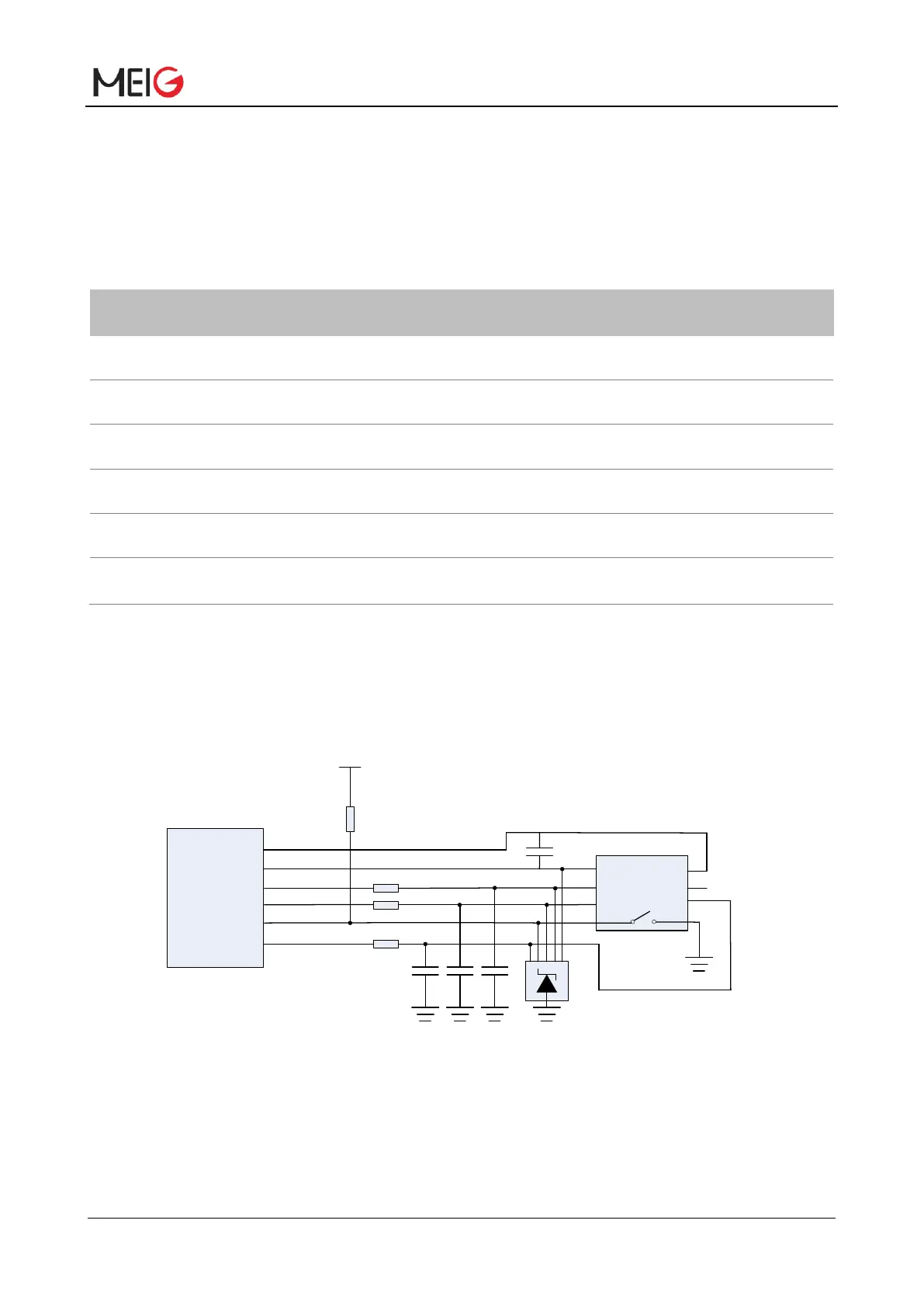
SLM770A module supports USIM hot plug through the USIM_PRESENCE pin and supports high level
detection. By default, the hot plug function is disabled. In the figure, the level of the USIM_PRESENCE
pin is high after the SIM card is inserted. When no card is detected, the level of the USIM_PRESENCE
pin is low.
Module
USIM_GND
USIM_VDD
USIM_RST
USIM_CLK
USIM_PRESENCE
USIM_DATA
VCC
RST
CLK
GND
VPP
IO
22R
22R
22R
GND
33PF 33PF 33PF
100nF
51K
VDD_EXT
USIM CARD CONNECTOR
Figure 14 Reference circuit for 8-pin USIM/SIM connector
If USIM card detection is not required, keep the USIM_PRESENCE pin open. The figure below is the
6-PIN USIM connector interface reference circuit


 To Next Page