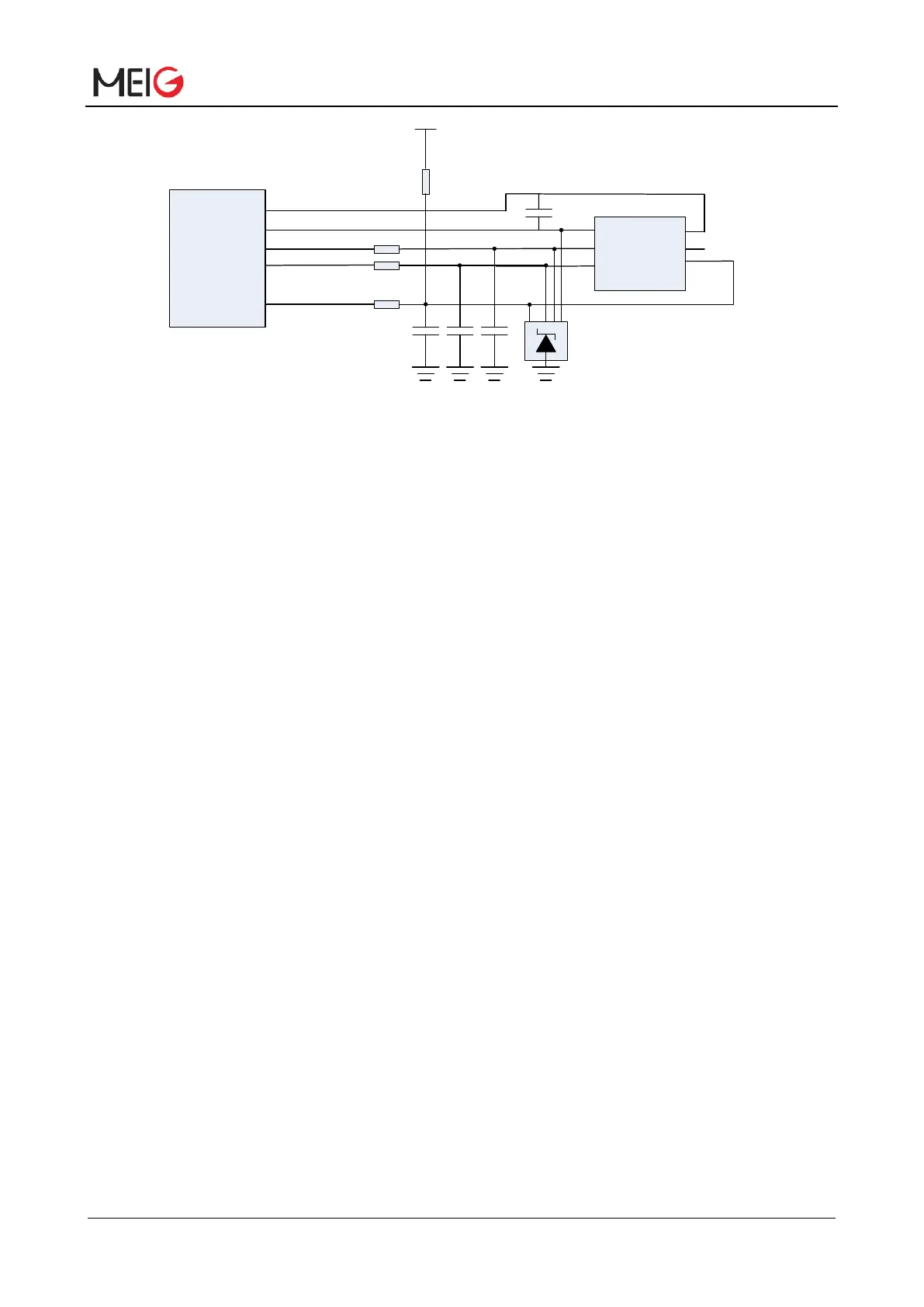
Figure 15 Reference circuit for 6-pin USIM/SIM connector
In order to enhance the reliability and availability of the USIM card in your application, please follow the
criteria below in the USIM circuit design:
⚫ USIM_DATA requires a pull-up resistor of 15kΩ to USIM_VCC; the pull-up resistor helps to increase
SIM card's anti-interference ability. When USIM card trace is too long or it is close to the interference
source, it is recommended that you add a pull-up resistor near the card.
⚫ In order to suppress stray EMI and enhance ESD protection, it is recommended to connect a
resistance of 22Ω on USIM_DATA, USIM_CLK and USIM_RESET line;
⚫ In order to improve the antistatic ability and offer good ESD protection, it is recommended to add
TVS whose parasitic capacitance should be less than 15pF on USIM_VCC, USIM_DATA,
USIM_CLK and USIM_RESET line;
⚫ In order to filter GSM900 interference, add a parallel 33pF resistance on USIM_VCC, USIM_DATA,
USIM_CLK and USIM_RESET line;
⚫ Keep layout of USIM card as close as possible to the module. Assure the length of signal wiring is
less than 200mm;
⚫ Keep USIM card signal away from RF and VBAT power line;
⚫ To avoid cross-talk between USIM_CLK and USIM_DATA, keep them away from each other and
shield them with surrounded ground;
⚫ For the USIM/SIM card hot-plugging function, the hot plugging pin is used to DETECT the pin and
the Pin13 pin of the module. The default hot plug function is off. Please contact us for more details.
Note: Not support hot plug SIM Connectors directly on USIM, SIM card hot plug, may cause (U) SIM
card or SLM770A (U) SIM interface damage.
3.10 USB Interface
The SLM770A provides a USB 2.0 compliant interface that supports both high speed (480Mbps) and full


 To Next Page