SLM770A Module Hardware Design Manual
MeiG Smart Technology Co., Ltd 77/77
⚫ AOUT channel is a differential output and is usually used for a handset
Design considerations:
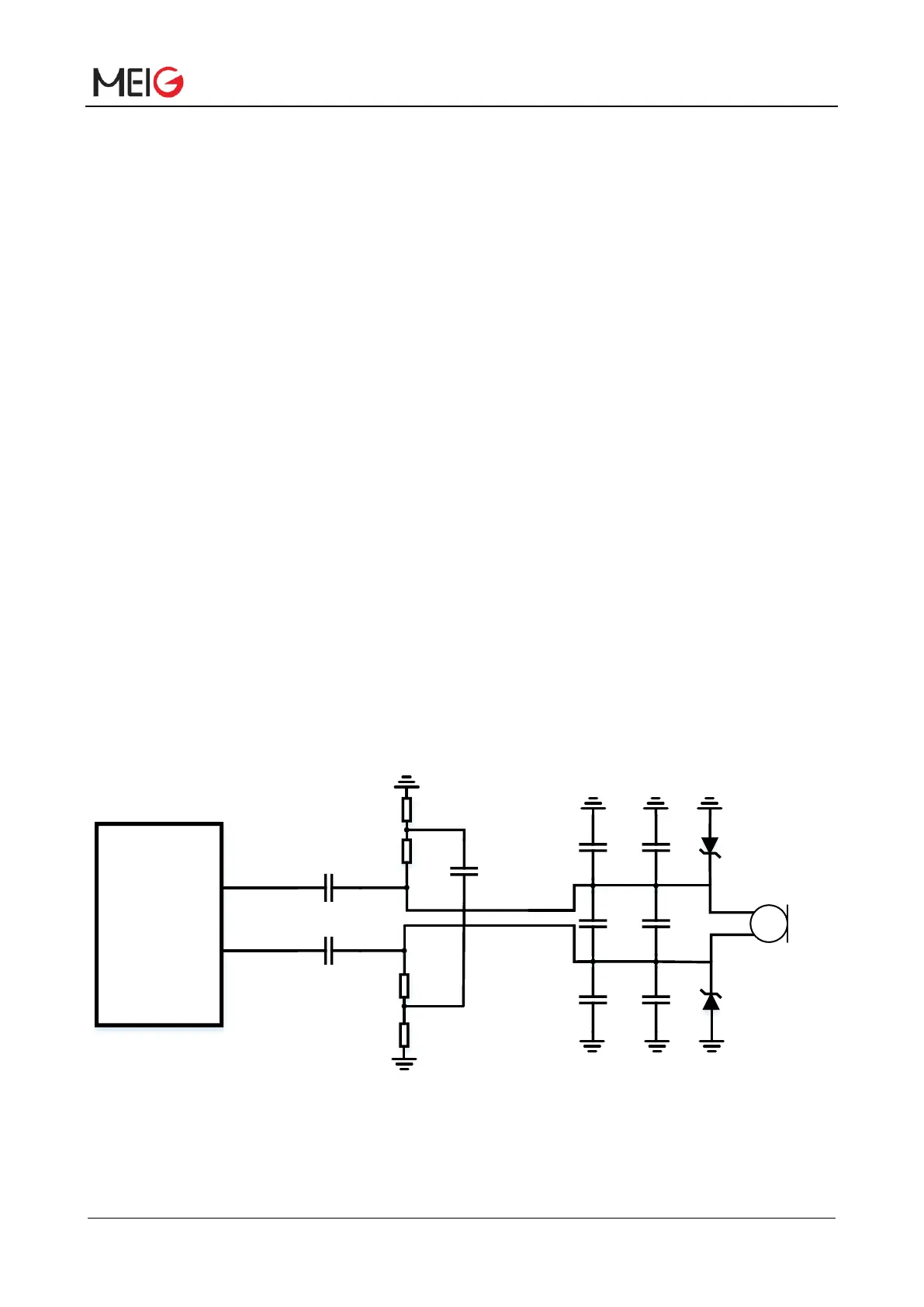
It is recommended to use electret microphone to filter out RF interference from the interference source,
which will greatly improve the coupled TDD noise. The 33pF capacitor is used to filter out high-frequency
interference caused by the module operating at the EGSM900 frequency. If the capacitor is not added,
TDD noise may be heard during calls. At the same time, the 10pF capacitor is used to filter out
high-frequency interference operating at the DCS1800 frequency. It should be noted that since the
resonant point of the capacitor is largely dependent on the capacitor material and the manufacturing
process, it is necessary to consult the capacitor supplier when selecting the capacitor and select the
most appropriate capacitance value to filter out the high-frequency noise operating at
EGSM900/DCS1800.
The severity of high-frequency interference during GSM transmission usually depends mainly on the
customer application design. In some cases, EGSM900 is TDD
The noise is more serious, and in some cases, the TDD noise of DCS1800 is more serious. Therefore,
customers can select the required filter capacitor according to the test results. The filter capacitor on the
PCB board should be placed as close as possible to the audio device or the audio interface, the line
should be as short as possible, and the filter capacitor should be first passed to other connection points.
To reduce radio or other signal interference, keep the RF antenna away from the audio interface and
audio wiring. The power cable should not be parallel to the audio cable and should be far away from the
audio cable. Differential audio routing must follow the routing rules of differential signals.
The reference interface circuit is as follows:


 To Next Page