2. Remove the two screws that secure the front cowl to the shift lever brackets.
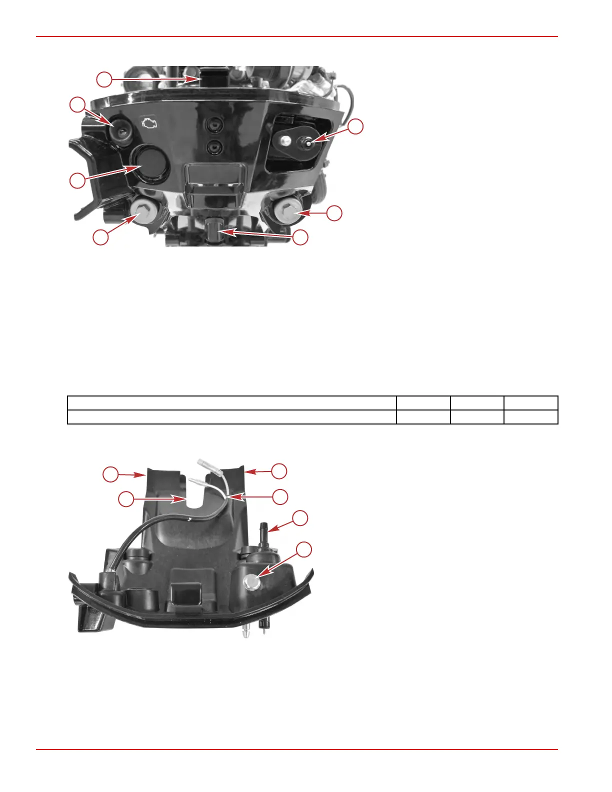
a - Screws (2)
b - Rubber plug (optional start push‑button)
c - Diagnostic light
d - Top cowl catch
e - Fuel connection
f - Upper shift shaft boot
3. Disconnect the two bullet connectors for the diagnostic light.
4. Disconnect the two bullet connectors for the start switch, if equipped.
5. Remove the fuel inlet hose from the fuel inlet fitting.
6. To remove the fuel inlet fitting, remove one screw.
Installation
1. If the fuel inlet fitting was removed, install it, and secure it with one screw.
2. Slide the cowl into position, ensuring that the tabs engage with the midplate and the upper shift shaft boot seats in the
notch in the front cowl.
3. Ensure that all of the grommets and washers are still in place, and secure the front cowl to the shift lever brackets with two
screws. Tighten the screws to the specified torque.
Description Nm lb‑in. lb‑ft
Front cowl screws 6.0 53.1 –
4. Connect the diagnostic light bullet connectors to the engine harness.
5.
Attach the fuel inlet hose to the fuel inlet fitting, and secure it with a spring‑type hose clamp.
a - Notch for upper shift shaft boot
b - Tabs for midplate
c - Bullet connectors for diagnostic light
d - Fuel inlet fitting
e - Screw securing fuel inlet fitting
6.
Install the driveshaft housing covers. Refer to Driveshaft Housing Covers.
Clamp/Swivel Bracket and Driveshaft Housing
Page 5A-18 © 2018 Mercury Marine 90-8M0125265 eng NOVEMBER 2017

 Loading...
