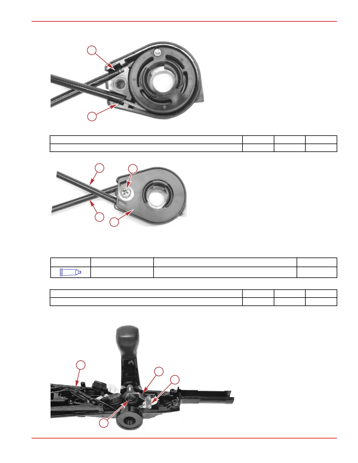
4. Ensure that the cable ends are fully installed in the case.
a - Cable ends installed in case
5. Hold the cables in place and install the cover with a screw. Tighten the screw to the specified torque.
Description Nm lb‑in. lb‑ft
Pulley cover screw 2.0 17.7 –
6. Rotate the pulley, and ensure that the cables move freely.
a - Throttle cable (2)
b - Pulley cover screw
c - Pulley cover
Tiller Handle Assembly
1.
Apply 2‑4‑C with PTFE to the shift handle bushings.
Tube Ref No. Description Where Used Part No.
95
2-4-C with PTFE Shift handle bushings 92-802859A 1
2. Attach the shift handle and cam to the tiller handle housing with a screw. Tighten the screw to the specified torque.
Description Nm lb‑in. lb‑ft
Shift handle screw 20.3 180 –
3. Power tilt models: Place the tilt switch into position in the tiller handle housing.
4.
Install the detent spring and secure it with two screws.
Power tilt model shown, manual tilt
model similar
a - Screws (2)
b - Shift detent spring
c - Tiller handle harness
d - Shift handle screw
Tiller Handle
90-8M0125265 eng NOVEMBER 2017 © 2018 Mercury Marine Page 7B-13

 Loading...
