Do you have a question about the Mercury 4-Stroke 9.9 HP and is the answer not in the manual?
Instructions for routing and installing the steering cable on the starboard side.
Guidance on applying grease and connecting the remote wiring harness to the outboard.
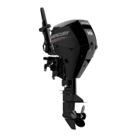
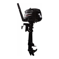
This manual describes the installation, operation, and maintenance of 9.9 and 15 HP (4-Stroke) outboards, providing comprehensive guidance for proper setup and care. It emphasizes safety precautions and correct procedures to ensure optimal performance and longevity of the marine engine.
The installation process begins with mounting the outboard to the boat's transom. It is crucial to measure the transom height accurately, ensuring that the boat bottom aligns with or is within 1 inch (25mm) above the anti-ventilation plate of the outboard. After positioning the outboard on the transom's center line, the transom clamp handles must be tightened securely. To prevent accidental loss of the outboard overboard, two 5/16 inch (7.9 mm) holes should be drilled through the transom using the clamp holes as a template. The outboard is then fastened with two bolts, flat washers, and locknuts, with a marine waterproofing sealer applied in and around the holes to ensure a watertight installation.
Connecting the steering cable is a critical step for proper boat control. For starboard-side routed cables, the entire cable end should be lubricated with Quicksilver 2-4-C Marine Lubricant with Teflon before inserting it into the tilt tube. The nut should then be torqued to 35 lb. ft. (47.5 N·m). Following this, the steering cable seal needs to be installed. A mark should be made 1/4 inch (6.4 mm) from the end of the tilt tube, and the seal components, including a plastic spacer, O-ring seal, and cap, should be installed. The cap is then threaded to the mark.
The steering link rod connects the steering cable to the engine, enabling directional control. It must be installed as illustrated, using a special bolt (Part Number 10-90041) and self-locking nuts (Part Number 11-34863). These locknuts are crucial and must never be replaced with common, non-locking nuts, as they can loosen and vibrate off, causing the link rod to disengage. Disengagement of the steering link rod can lead to a sudden, sharp turn of the boat, potentially throwing occupants overboard and causing serious injury or death. The special bolt should be torqued to 20 lb. ft. (27.1 N·m), and the nylon insert locknut should be tightened until it seats, then backed off 1/4 turn. The middle hole should be used for connection.
The wiring harness connects the remote control to the engine. Quicksilver Dielectric Grease should be applied inside the connection before plugging the remote wiring connector into the outboard wiring harness connector. A retainer then secures the connection.
Battery cable connections are detailed for both single and dual outboard configurations. For a single outboard, the red sleeve (positive) cable connects to the positive terminal of the starting battery, and the black sleeve (negative) cable connects to the negative terminal. For dual outboards, a common ground cable, with the same wire size as the engine battery cables, connects between the negative (-) terminals on the starting batteries.
The shift and throttle cables are installed into the remote control first, following the instructions provided with the control. It is important to install the shift cable to the engine first, as it is the initial cable to move when the remote control handle is shifted out of neutral. For shift cable installation, the remote control is positioned into Forward gear, and the cover is removed. The outboard is then shifted into forward gear by rotating the shift arm forward. The cable is installed to the shift lever and secured with a cable latch. The cable barrel is adjusted to fit into the anchor pocket. A crucial adjustment check involves shifting the remote control into forward, neutral, and reverse while turning the propeller. In forward and reverse, the propeller shaft should be locked in gear. In neutral, it should turn freely without drag. Adjustments to the barrel are made to achieve these conditions.
For throttle cable installation, the remote control is positioned into neutral. The throttle cable is installed on the pin and locked with a cable latch. The cable barrel is adjusted until the link rod is centered in the slot. After installation, the remote control handle should be moved a few times from neutral to wide-open-throttle in forward gear, then back to neutral, visually checking that the link rod remains centered. If necessary, the barrel is readjusted. Finally, the cover is reinstalled.
Propeller installation varies slightly between standard gear cases and Big Foot gear cases. For both types, a critical safety warning is provided: if the propeller shaft is rotated while the engine is in gear, the engine may crank over and start. To prevent accidental starting and serious injury from a rotating propeller, the outboard must always be shifted to neutral position, and spark plug leads removed when servicing the propeller.
For Flo-Torq I Drive Hub Propellers (Standard Gear Case), the forward thrust hub, propeller, rear thrust hub, and propeller nut are installed. The propeller nut is then tightened. For Flo-Torq II Drive Hub Propellers (Standard Gear Case), the forward thrust hub, replaceable drive sleeve, propeller, rear thrust hub, and propeller nut are installed and tightened.
Similarly, for Big Foot Gear Case with Flo-Torq I Drive Hub Propellers, the forward thrust hub, propeller, and propeller nut are installed and tightened. For Flo-Torq II Drive Hub Propellers (Big Foot Gear Case), the forward thrust hub, replaceable drive sleeve, propeller, rear thrust hub, and propeller nut are installed and tightened.
The manual also includes important general information regarding boat horsepower capacity. It advises against overpowering or overloading the boat, referencing the U.S. Coast Guard capacity plate that indicates maximum acceptable horsepower, person capacity (pounds), and weight capacity. Overpowering a boat can lead to loss of control, excessive weight at the transom altering flotation characteristics, or even structural damage to the boat, particularly around the transom area, potentially resulting in serious injury, death, or boat damage.
A key safety feature highlighted is "Start in Gear Protection." The remote control connected to the outboard must be equipped with a device that prevents the engine from starting when in gear. This design prevents sudden, unexpected acceleration, which could cause serious injury or death.
When selecting accessories for the outboard, the manual recommends using Genuine Quicksilver Parts and Accessories, as they are specifically designed and tested for this outboard. Accessories not manufactured or sold by Quicksilver may not be safely used with the outboard or its operating system. Users are advised to acquire and read the installation, operation, and maintenance manuals for all selected accessories.
Overall, this manual serves as an essential guide for ensuring the safe and effective installation, operation, and maintenance of 9.9 and 15 HP (4-Stroke) outboards, emphasizing safety, proper procedures, and the use of compatible components.
| Engine Type | 4-Stroke |
|---|---|
| Horsepower | 9.9 HP |
| Cylinders | 2 |
| Starting System | Manual or Electric |
| Weight | 84 lbs (38 kg) |
| Full Throttle RPM Range | 5000-6000 RPM |
| Gear Ratio | 2.08:1 |
| Fuel Induction System | Single Overhead Cam (SOHC) |
| Shaft Length | 15" / 20" |
| Steering | Tiller or Remote |
| Fuel Type | Unleaded Gasoline |
| Alternator Output | 6 Amps |