90-830234R3 DECEMBER 1997 ELECTRICAL - 2D-25
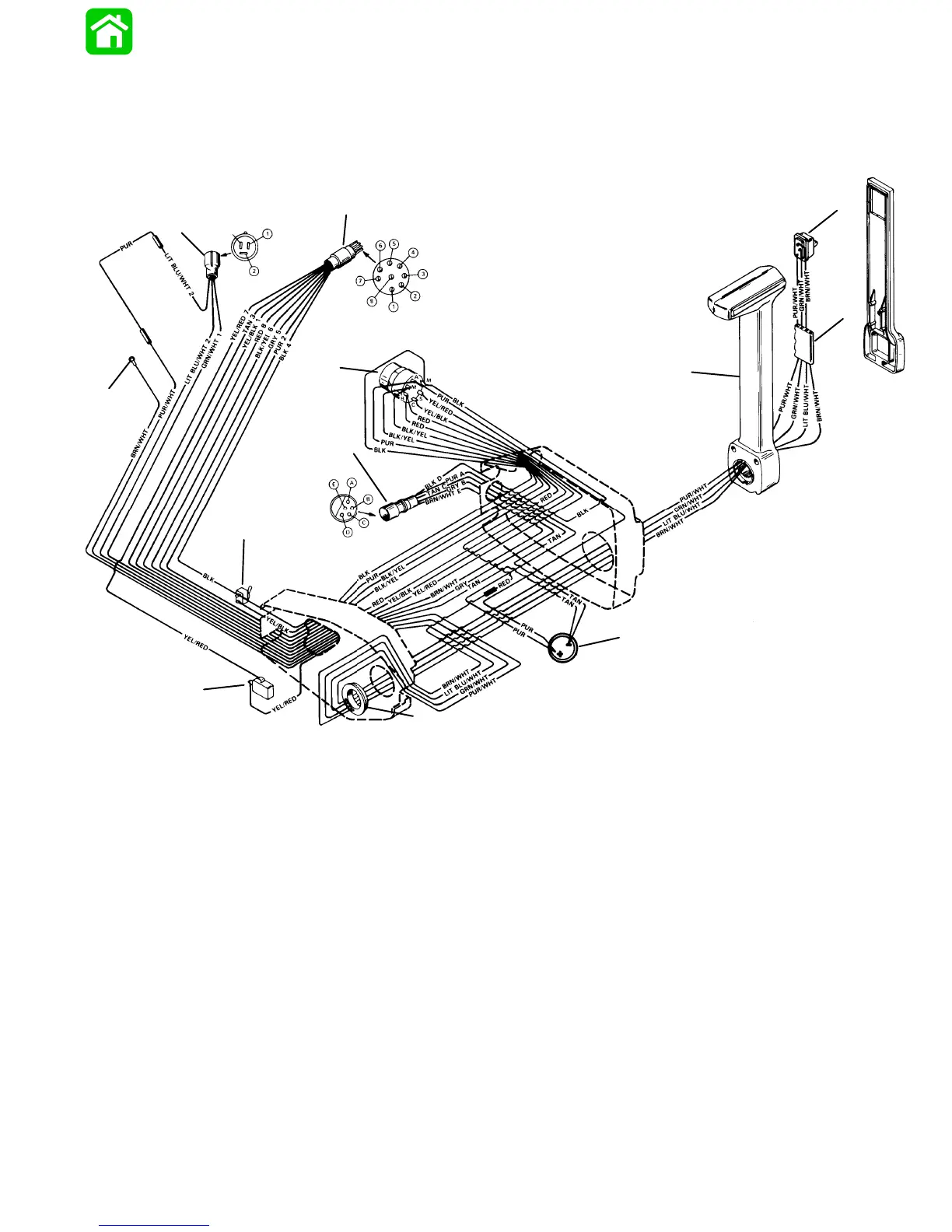
COMMANDER 2000 Side Mount Remote Control
(Power Trim/Tilt Electric Start with Warning Horn) Wiring Diagram
24072
g
h
i
f
d
a
e
k
l
b
c
j
BLK = BLACK
BLU = BLUE
BRN = BROWN
GRY = GRAY
GRN = GREEN
PUR = PURPLE
RED = RED
TAN = TAN
VIO = VIOLET
WHT = WHITE
YEL = YELLOW
a - Ignition/Choke Switch
b - Emergency Stop Switch
c - Neutral Start Switch
d - Tachometer/Accessories Harness Connector
e - Wiring Harness Connector
f - Warning Horn
g - Trim/Tilt Switch
h - Wire Retainer
i - Control Handle
j - Trim Harness Bushing
k - Trim Harness Connector
l - Lead to Trim Indicator Gauge
 Loading...


