Section 5 - Maintenance
Page 30 90-899883210 APRIL 2008
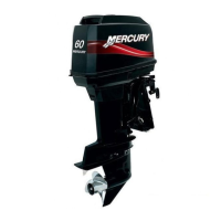
3. Install the propeller. Rotate the propeller until it is fully seated on the propeller pin. If a dual propeller
model, position the propellers so that the blades of one propeller can be seen between the blades of
the other.
a - Propeller shaft
b - Propeller hub
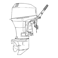
4. Tighten the fixing screws on the cap. The screws must not protrude more than 2 mm (5/64 in.) from
the hub of the propeller. If the screws protrude more than 2 mm (5/64 in.) from the hub, the propeller
is not correctly seated against the propeller pin.
a - Wrench
b - Fixing screw
c - Propeller hub
Description Nm lb‑in. lb‑ft
Thruster models CT60, CT80, and CT125 1.5 13 –
Thruster models CT165 and CT225 7 61 –
!
CAUTION
Disconnecting or connecting the battery cables in the incorrect order can cause injury from electrical
shock or can damage the electrical system. Always disconnect the negative (‑) battery cable first and
connect it last.
5. Attach the negative battery cable to the thruster battery bank.
NOTICE
Operating the thrusters out of water for any amount of time can damage the motors or seals. Perform
tests only with the thrusters completely submerged in water to prevent damage.
6. Do not test the thrusters until the boat is back in the water.