Powerhead
90-8M0065421 NOVEMBER 2012 Page 4A-43
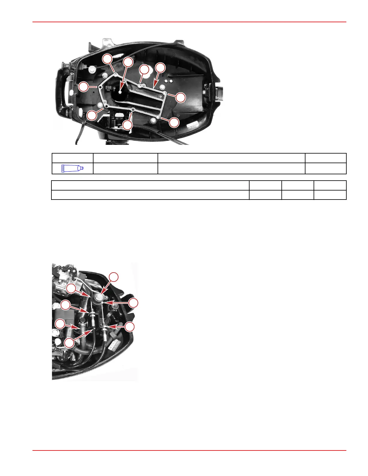
7. Secure the powerhead to the driveshaft housing with seven bolts. Tighten the bolts in sequence to the specified torque.
a - Driveshaft
b - Gasket surface
Tube Ref No. Description Where Used Part No.
95
2-4-C with PTFE Driveshaft splines 92-802859A 1
Description Nm lb‑in. lb‑ft
Powerhead mounting bolts (M6 x 35) (7) 11 97
8.
Install the flywheel and flywheel cover. Refer to Section 2A ‑ Ignition.
9.
Adjust the valve clearance. Refer to Valve Clearance Adjustment.
10.
Install the carburetor. Refer to Section 3A ‑ Carburetor and Fuel Pump.
11.
Install the ignitor. Refer to Section 2A ‑ Ignition.
12. Install the throttle drum and cable bracket.
13.
Install the throttle cables. Refer to Section 7B ‑ Tiller Handle.
14. Install the fuel pump pulse hose onto the fitting on the intake manifold.
a - Throttle drum bolt (M6 x 35)
b - Throttle cable ends
c - Jam nuts (two per cable)
d - Match mark on acceleration throttle cable
e - Fuel pump pulse hose
f - Throttle drum
15. Attach the fuel pump to the carburetor inlet hose and the fuel pump to fuel shutoff hose. Secure the hoses with hose
clamps.
IMPORTANT: Route the hoses as shown.
16. Install the fuel shutoff valve and hoses along the side of the powerhead.
• Align fuel shutoff valve with the fuel shutoff knob
• The fuel hose to the fuel tank snaps into the bracket attached to the cylinder block
 Loading...