EasyManua.ls Logo

Mercury SCC-1 - User Manual

Mercury SCC-1
23 pages
To Next Page IconTo Next Page
Loading...
SCC-1 SMARTCRAFT CONNECT GATEWAY
INSTALLATION MANUAL
IMPORTANT:This document guides our dealers, boatbuilders, and company service personnel in the proper installation
or service of our products. If you have not been trained in the recommended servicing or installation procedures for
these or similar Mercury Marine products, have the work performed by an authorized Mercury Marine dealer technician.
Improper installation or servicing of the Mercury product could result in damage to the product or personal injury to
those installing or operating the product. Always refer to the appropriate Mercury Marine service manual for component
removal and installation instructions.
NOTE:
After completing installation, place these instructions with the product for the owner's future use.
Components in Kit
NOTE:The termination band on the 10‑pin connector cable only applies to engine‑mounted modules.
a - SmartCraft CONNECT module
b - SmartCraft CONNECT module ‑ side view
c - Cable ties ‑ 4
d - #10 x .88" stainless steel wood screw
Features
The CAN P, CAN H, and NMEA lights will turn on when data is being transmitted through the gateway.
NOTE:This manual covers the installation of CAN P only ‑ engine‑mounted module (single). The helm‑mounted module
will default out of the box with CAN P and CAN H. CAN H is applicable to dual, triple, and quad DTS engine applications.
CAN H must be turned off if issues with the analog tachometers are encountered on mechanical/non‑DTS products.
a
b
c
d
71911
TERMINA
TED
ENGINE MOUNT ONL
Y
90-8M0219240 eng MAY2023 © 2023 Mercury Marine Page1 / 23
8M0219240 523 eng
Question and Answer IconNeed help?

Do you have a question about the Mercury SCC-1 and is the answer not in the manual?

Mercury SCC-1 Specifications

General IconGeneral
BrandMercury
ModelSCC-1
CategoryGateway
LanguageEnglish

Summary

Components in Kit

Kit Contents Overview

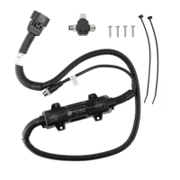
Lists the primary components of the kit: the SmartCraft CONNECT module and mounting hardware.

SmartCraft CONNECT Module Features

Indicator Light Functions

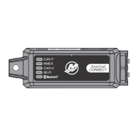
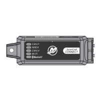
Explains the meaning of the CAN P, CAN H, and NMEA indicator lights.

CAN H Usage Notes

Details the applicability of CAN H for specific engine configurations.

Module Harness Connections

Connection Methods

Describes the two methods for connecting the SmartCraft CONNECT module harness.

On-Engine Mounting Guidelines

General Mounting Requirements

Outlines critical requirements for mounting the module on an engine, including bend radius and securing.

Location Avoidance

Lists specific locations on the engine to avoid when installing the SmartCraft CONNECT module.

FourStroke EFI Mounting Procedure

Details the specific steps for mounting the module on a 25/30 FourStroke EFI engine.

Mercury Avator 7.5 e Mounting

Avator 7.5 e Installation Overview

Provides an introduction to installing the SmartCraft CONNECT on Mercury Avator models.

Serial Number Recording

Instructs users to record the SmartCraft CONNECT serial number before installation.

Component Removal for Avator

Details the removal of panels and battery for Avator mounting access.

Connecting Harness on Avator

Explains how to connect the 10-pin connector and secure the harness on the Avator outboard.

Module Configuration Process

Consumer Configuration Overview

Guides users through app download, Bluetooth setup, and user selection.

Wi-Fi Network Connection

Details the process of selecting and connecting to a Wi-Fi network for module configuration.

Firmware Update Procedure

Explains how to check for and perform firmware updates for the SmartCraft CONNECT module.

Engine and Tank Configuration

Covers configuring engine details, gateways, and tank information using the app.

Steering and Stationkeeping Setup

Details how to configure steering angle source and stationkeeping features.

Mercury Dealer or OEM Configuration Process

Dealer Configuration Steps

Outlines the process for dealers and OEMs to configure the module using license information.

Account Sign-in and Creation

Guides users on signing into or creating a Mercury account for configuration.

LED Lighting and Status

LED Indicator Meanings

Explains the status indicated by the LEDs for CAN P, NMEA, CAN H, Wi-Fi, and Bluetooth.

Wi-Fi LED Status Troubleshooting

Details troubleshooting steps based on the Wi-Fi LED status.

Firewall and Licensing

Required Firewall Ports

Lists the web domains and ports that must be open for proper module operation.

Licensing Error Explanations

Describes common licensing errors and their meanings.

NMEA 2000 Information

NMEA 2000 Network Power

Provides information on the NMEA 2000 Load Equivalency Number.

Transmitted NMEA 2000 PGNs

Lists the Parameter Group Numbers (PGNs) transmitted by the module.

Received NMEA 2000 PGNs

Lists the Parameter Group Numbers (PGNs) received by the module.

Engine Data to NMEA 2000

Details engine data signals transmitted to NMEA 2000 devices.

Regulatory Information

FCC and ISED Compliance

Outlines the device's compliance with FCC and ISED regulations.

RF Exposure Considerations

Provides guidance on RF exposure limits and antenna installation requirements.

Related product manuals