18
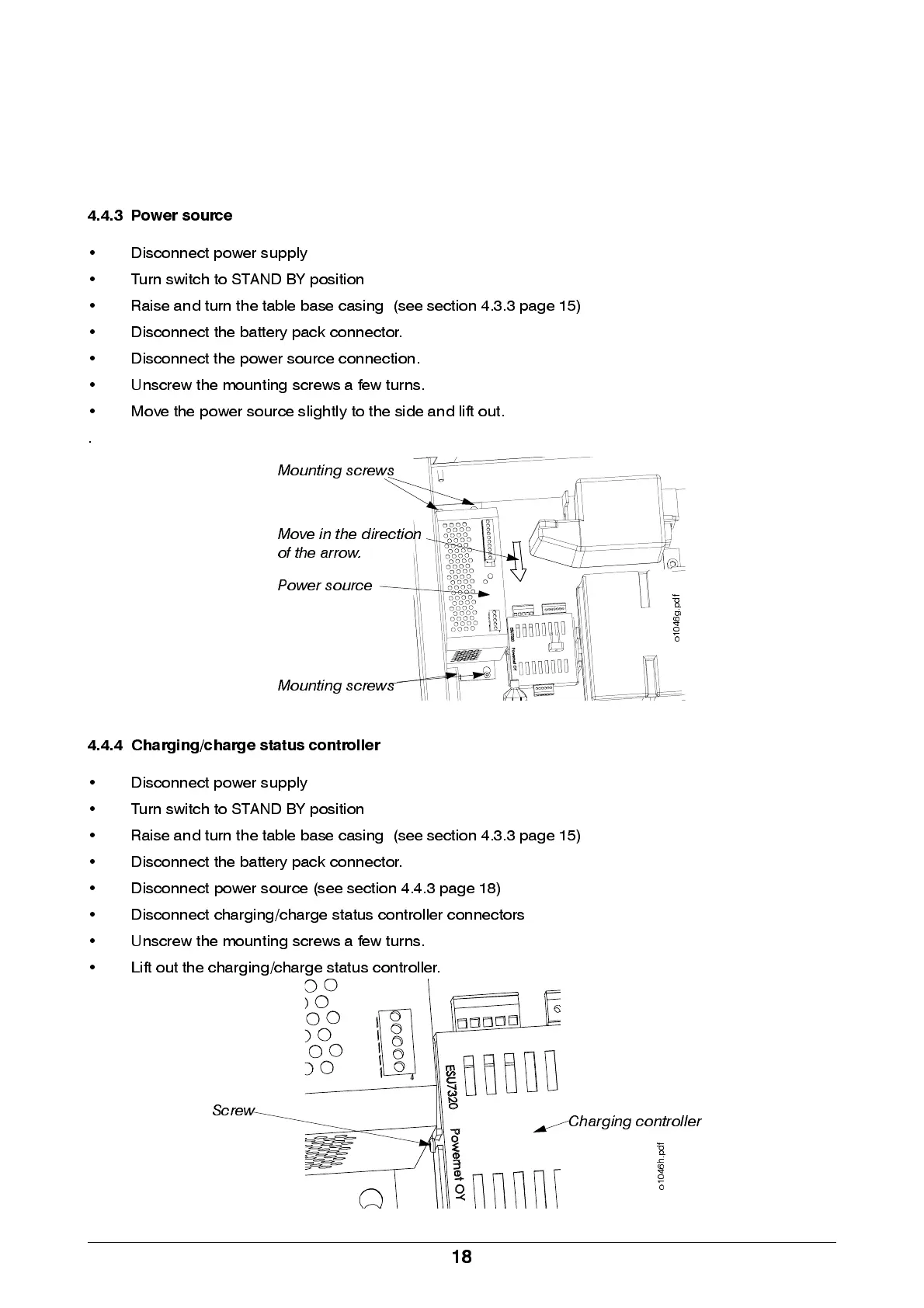
4.4.3 Power source
• Disconnect power supply
• Turn switch to STAND BY position
• Raise and turn the table base casing (see section 4.3.3 page 15)
• Disconnect the battery pack connector.
• Disconnect the power source connection.
• Unscrew the mounting screws a few turn s.
• M ove the power source slightly to the side and lift out.
.
4.4.4 Charging/charge status controller
• Disconnect power supply
• Turn switch to STAND BY position
• Raise and turn the table base casing (see section 4.3.3 page 15)
• Disconnect the battery pack connector.
• Disconn ect power source (see section 4.4.3 page 18)
• Discon n e ct chargi ng / cha rge sta tus controlle r conn e ctors
• Unscrew the mounting screws a few turn s.
• Lift out the charging/charge status controller.
Mounting screws
Mounting screws
Power source
o
1
0
4
6
g
.
p
d
f
Move in the direction
of the arrow.
Screw
Charging controller
o
1
0
4
6
h
.
p
d
f