24
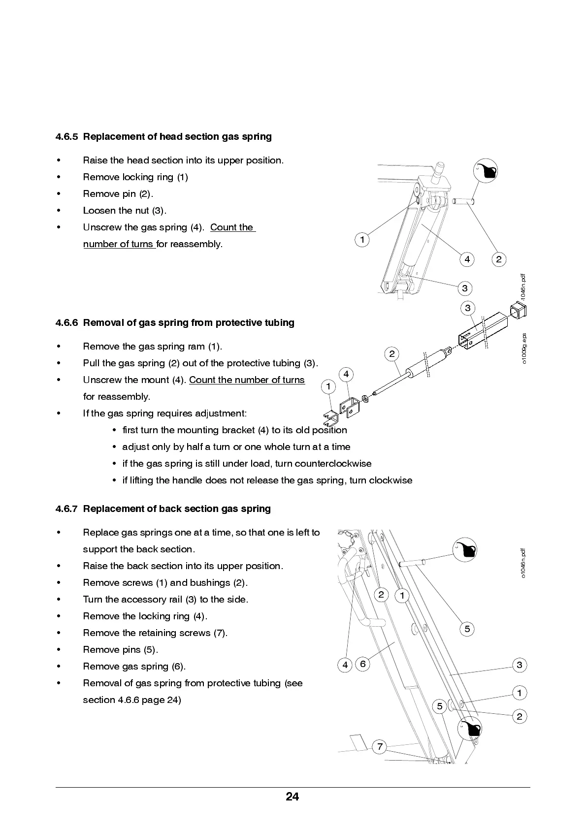
4.6.5 Replacement of head section gas spring
• Raise the head s ection into its up p er po sition.
• Remove locking ring (1)
• Remove pin (2).
• Loosen the nut (3).
• Unscrew the gas spring (4). Count the
number of turns for reassembly.
4.6.6 Removal of gas spring from protective tubing
• Re move the ga s sp rin g ram (1).
• Pull the gas spring (2) out of the protective tubing (3).
• Unscrew the moun t (4). Count the number of turns
for reassembly.
• If the gas spring requires adjustment:
• first turn the mounting bracket (4) to its old position
• adjust only by half a turn or one whole turn at a time
• if the gas spring is still under load, turn counterclockwise
• if lifting the handle does not release the gas spring, turn clockwise
4.6.7 Replacement of back section gas spring
• Rep la ce gas spr i ngs on e at a tim e, s o t ha t o ne i s lef t t o
sup p ort the ba ck se ction .
• Raise the back section into its upper position.
• Remove screws (1) and bus hings (2).
• Tu rn the ac ces s ory rail (3) to th e si de .
• Remove the locking ring (4).
• Remove the retaining screws (7).
• Remove pins (5).
• Remove gas spring (6).
• Removal of gas spring from protective tubing (see
se ction 4.6.6 pag e 24)
3
1
24
o
1
0
4
6
n
.
p
d
f
o
1
0
0
9
g
.
e
p
s
1
2
3
4
1
6
5
2
1
34
2
5
o
1
0
4
6
n
.
p
d
f
7