26
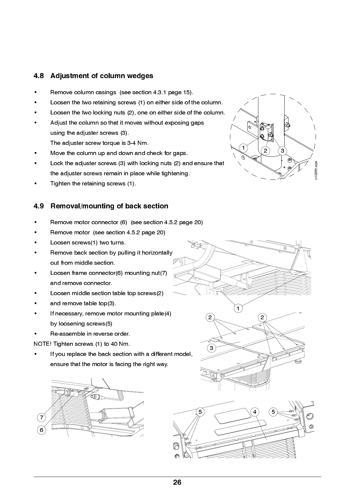
4.8 Adjustment of column wedges
• Re m ove colu m n cas in g s (see se ction 4.3.1 p ag e 15).
• Loosen the two retaining screws (1) on either side of the column.
• Loose n the two lock ing nu ts (2), one on e ithe r sid e of th e colu mn .
• Adjust the column so that it moves without exposing ga ps
using the adjuster screws (3).
The adjuster screw torque is 3-4 Nm.
• Move the column up and down and check for gaps.
• Lo ck the adj uster screws (3) with locking nuts (2) and ensure that
the ad j us ter scre ws rem ain in p la ce wh ile tigh ten in g .
• Tig hte n the retain ing screws (1).
4.9 Removal/mounting of back section
• Remove motor connector (6) (see section 4.5.2 page 20)
• Remove motor (see section 4.5.2 page 20)
• Loosen screw s(1) two turns.
• Re m ove ba ck se ction b y pu llin g it horizo nta lly
out from middle s ection.
• Loosen frame connector(6) mounting nut(7)
and remove connector.
• Loosen middle section table top screws(2)
• and remove table top(3).
• If necessary, remove motor mounting plate(4)
by loosening screws(5)
• Re -as se m b le in reve rs e ord er.
NOTE! Tighten screws (1) to 40 Nm.
• If you repla ce the ba ck se ction with a di ffere n t mod el ,
ensure tha t the motor is facing the righ t way.
3
1
2
o
1
0
2
6
h
.
e
p
s
2
1
2
45 5
3
7
6