Mechanical installation Page 17
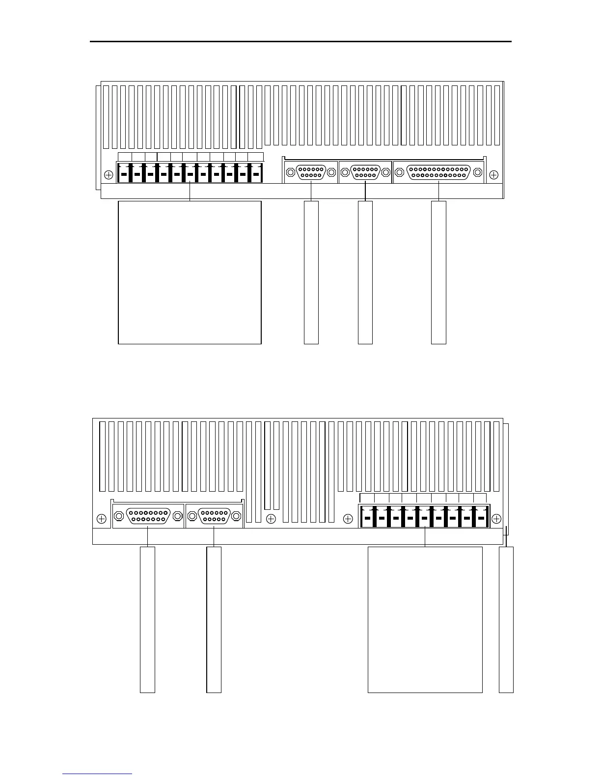
[X11]: Incremental encoder output
[X10]: Incremental encoder input
[X1]: I/O interface
[X1] I/O[X10] IN[X11] OUT
[X9.]
PEBR-INTBR-CH
BR-EXT
ZK-ZK+L3L2L1
+24V GND24V
Power Supply [X9]:
L 1: mains phase 480VAC
L 2: mains phase 480VAC
L 3: mains phase 480VAC
ZK+: pos. DC bus voltage
ZK-: neg. DC bus voltage
BR-EXT: extern brake chopper
BR-CH: brake chopper
BR-INT: intern brake chopper
PE: ground conductor from
mains
+24V: 24VDC
GND24V: GND 24VDC
Figure 2: Servo positioning controller ARS 2302 FS: Top view
Motor Connection [X6]:
BR-: holding brake
BR+:
holding brake
PE: inner shield
MT-:
motor sensor
MT+ motor sensor
PE:
motor ground conductor
W: motor phase 3
V: motor phase 2
U: motor phase 1
[X2A]: Connection for the resolver
[X2B]: Connection for the encoder
[X6.]
[X2A] RESOLVER
[X2B] ENCODER
UVWPEMT+MT-PEBR+BR-
Connection for the shield
Figure 3: Servo positioning controller ARS 2302 FS: Bottom view