EasyManua.ls Logo

Metrotech 810 Line Tracer - User Manual

Metrotech 810 Line Tracer
28 pages
Print Icon
To Next Page IconTo Next Page
Loading...
810™ Line Tracer
OPERATIONS MANUAL
SERVICE CENTER, SALES AND TECHNICAL SUPPORT INFORMATION
Corporate Headquarters Metrotech Eastern U.S. Service Center Metrotech European Service Center
3251 Olcott Street 5211 Linbar Drive, Suite 503 Seba KMT
Santa Clara, CA 95054 Nashville, TN 37211 Dr. Herbert Iann St. 6
800-446-3392 800-624-6210 96148 Baunach, Germany
408-734-1400 Direct 615-366-7323 Direct +49 9 544 680
408-734-1415 Fax 615-360-9855 Fax +49 9 544 2273 Fax
www.metrotech.com
nashville@metrotech.com service@sebakmt.com
sales@metrotech.com
Warranty: One year. Specifications Subject to change without notice, ISO 9001:2000 Certified. Copyright 2008. All Rights Reserved revision:11/06/08
Question and Answer IconNeed help?

Do you have a question about the Metrotech 810 Line Tracer and is the answer not in the manual?

Summary

Introduction to the Metrotech 810 Line Tracer

Metrotech 810 Line Tracer Equipment

Standard Equipment

Lists the standard components included with the 810 Line Tracer system.

Optional Equipment

Details optional accessories available for the 810 Line Tracer.

Technical Specifications

Provides detailed technical specifications for the 810 Transmitter and Receiver.

Transmitter Controls and Indicators

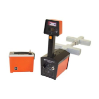
Explains the controls and indicators on the 810 Transmitter unit.

Receiver Controls and Indicators

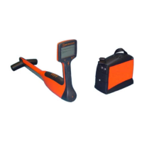
Explains the controls and indicators on the 810 Receiver unit.

Checkout Procedure for 810 Line Tracer

Operating the 810 Line Tracer

Transmitter Direct Connection

Procedure for applying signal using the direct connection method.

Transmitter Inductive Coupling

Procedure for inducing signal using the Metroclamp and inductive coupling.

Transmitter Inductive Method

Procedure for inducing signal using the transmitter's internal antenna.

Using the Receiver

Instructions for operating the 810 Receiver to trace signals.

Determining Conductor Depth

Steps to accurately measure the depth of a conductor.

Ground Survey Procedure

Ground Survey Applications

Situations requiring a ground survey before excavation near utilities.

Locating Conductors During Ground Survey

Method for locating and marking known utilities during a ground survey.

Subdividing Large Search Areas

Technique for efficiently searching large areas by dividing them.

Tracing Techniques and Helpful Information

Soil Conditions Impact on Tracing

Effect of different soil types on line tracing performance.

Adjacent Conductor Interference

How to identify and mitigate interference from nearby conductors.

Grounding Safety Precautions

Essential safety precautions related to grounding procedures.

Detecting Ghost Conductors

Identifying and avoiding false traces caused by nearby conductors.

Maintenance of the 810 Line Tracer

Receiver Calibration

Procedure for calibrating the 810 Receiver and monitoring performance.

Replacing Receiver Batteries

Step-by-step guide for replacing batteries in the 810 Receiver.

Replacing Transmitter Batteries

Step-by-step guide for replacing batteries in the 810 Transmitter.

Metrotech Service Centers

Contact information for Metrotech service centers for equipment support.

Equipment Warranty Information

Overview

The Metrotech Model 810 Radio Frequency Line Tracer is a versatile instrument designed for tracing water and gas distribution lines, cables, and for inductive locating and blind searching. It utilizes a high-frequency signal that can effectively penetrate soil and bypass insulators and rubber gaskets commonly found in utility systems. The "floodlight" quality of its RF signal allows it to induce a signal onto conductors 8-10 feet on either side of the transmitter, making it suitable for blind searches.

Function Description

The 810 Line Tracer operates by generating a signal from its transmitter and applying it to a pipe or cable (conductor). This signal travels along the conductor, gradually weakening with distance from the transmitter. The receiver then detects this signal when positioned over the conductor. The receiver's Left/Right Guidance System, field strength display, and audio tone assist in tracing the conductor's path. A push-button feature allows for quick depth determination of the conductor. The Model 810 incorporates automatic impedance matching, which compensates for variations in soil conditions, conductor size, and material, ensuring consistent performance. It is designed exclusively for locating metallic conductors.

Important Technical Specifications

Transmitter:

  • Output Power: 250mW
  • Output Frequency: 83.0775kHz ± .002% (Crystal controlled for interference resistance)
  • Battery Type: Six NEDA 13F "D" Cells, Alkaline
  • Battery Life: 150 hrs. average
  • Battery Check: Power on, push Power Test button
  • Operation Temperature: 0 to 110°F (-18 to 43°C)
  • Weight: 3.9 lbs. (1.8 kg)
  • Dimensions: 8"L x 3.25"W x 6.5"H (20.3 x 10.5 x 17.2 cm)

Receiver:

  • Trace Accuracy: ±1 inch from 0 to 3 ft (91 cm) in depth; ±3% over 3 ft (91 cm) in depth
  • Depth Readout Accuracy: ± 10% under normal conditions
  • Depth Readout Range: To 13 ft. (400 cm)
  • Sensitivity Control: Automatic, no adjustments necessary
  • Battery Type: Four NEDA 1604A Alkaline (9V), IEC 6LR61 (Int'l Std.), or JIS 6AM6 (Jpn Std)
  • Battery Life: 145 hrs. average
  • Battery Check: Turn Mode Switch to Batt Test
  • Operation Temperature: 0 to 110°F (-18 to 43°C)
  • Weight: 4.1 lbs. (1.9 kg)
  • Dimensions (extended length): 32.5"L x 7.25"W x 12.25"H (82.6 x 18.4 x 31.1 cm)

Usage Features

The 810 Line Tracer offers three primary methods for applying a signal to a conductor:

  1. Direct Connection: This is the preferred method for its strong maximum signal and reduced adjacent buried conductor interference. It involves directly connecting the transmitter to a metallic part of the conductor (e.g., hydrant, meter, riser, valve, sheath, tracer wire) using the Direct Connect Cable and a ground spike or plate. The transmitter should be positioned at a right angle to the conductor, and the ground lead extended as far as possible.

  2. Inductive Coupling with a Metroclamp: Used when direct connection is not feasible but a Metroclamp can be positioned around the conductor. The Metroclamp induces a signal onto the conductor. This method requires the conductor to be well-grounded at both ends. Jumper cables are used to bypass insulators.

  3. Inductive Method: This is the least preferred method as the signal is broadcast through both soil and air, potentially being picked up by other conductors. It uses the internal antenna of the transmitter to induce a signal electromagnetically. The transmitter is positioned over the target conductor, at least 30 feet away from the receiver, with its CONDUCTOR DIRECTION arrow aligned with the conductor. Air coupling can be identified if the signal does not decrease when the receiver is raised above the conductor.

Receiver Operation:

  • Guidance System: The Left/Right Guidance Meter, signal strength, and audio tone guide the user. A needle moving right with a steady tone indicates the conductor is to the right; a needle moving left with a pulsing tone indicates the conductor is to the left. The signal strength on the LCD rises as the receiver approaches the conductor.
  • Pinpointing: As the receiver centers over the conductor, the needle moves to the center, the signal peaks, and the tone becomes silent.
  • Direction Determination: Touching the receiver tip to the ground over the conductor and rotating it on its vertical axis reveals the conductor's direction by the highest signal strength reading.
  • Depth Measurement: With the MODE SWITCH in the line-tracing mode, pressing the DEPTH button provides a stable depth reading on the LCD in inches or centimeters. A field strength greater than 500 is recommended for accurate depth measurements.
  • Conductor Identification (with a second Metroclamp): For multiple exposed conductors, a second Metroclamp plugged into the receiver's AUX INPUT can be used. By placing the Metroclamp around each conductor, the one with the highest field strength reading is the target.

Ground Survey Procedure:

  • For ground surveys, the Direct Connect method is most accurate for known utilities. For blind searches, the Inductive method with two operators (one with the transmitter, one with the receiver) moving in parallel across and down the survey area is recommended. The receiver operator moves sideways, facing the transmitter operator.
  • Large search areas should be subdivided for thorough sweeping.

Tracing Techniques and Helpful Information:

  • Soil Conditions: Moist, compact soil is ideal for tracing, while dry, sandy, rocky, alkaline, or high iron content soils can create poor tracing environments.
  • Adjacent Conductors: Interference from adjacent or parallel conductors can cause the field strength to drop off on one side. The ground lead should be positioned perpendicular to the tracing direction and away from adjacent conductors.
  • Metroclamp Grounding: Both ends of the target conductor must be grounded for sufficient field strength. Jumper cables are used to bypass insulated joints.
  • Deep Conductors: Signals from deep buried cables are weaker and less directional. Direct Connection is recommended for best results with deep conductors.
  • Field Strength: Optimum tracing accuracy is achieved with a field strength between 975 and 500.
  • "Ghost" Conductors: An apparent trace between two conductors due to signal pickup by both. Detected by changes in needle direction, tone, and illogical depth readings. To correct, backtrack and search in a 180-degree arc.
  • Completing the Circuit Path: A complete circuit path between the transmitter and receiver is essential. Breaks can be caused by disconnected leads, circuit breakers, or open switches.
  • Common Bonded Conductors: If other conductors are connected to the target, they may carry the same signal. Verify by noting gradual changes in field strength and depth readings.
  • Congested Areas: Requires careful judgment and comparison depth/field strength readings to differentiate target conductors from interfering ones. To reduce interference, change the transmitter coupling point/mode, improve grounding, or re-position the transmitter (especially in Inductive mode, placing it on its end over the interfering conductor).
  • Locating Service Laterals: Easiest in Inductive Mode with two operators. One operator remains stationary with the receiver over the main, while the other walks parallel with the transmitter (100 ft minimum distance) 5 feet from the main. Increased field strength indicates a lateral.
  • Valves, Manhole Covers, Tees, Risers: Sudden increases and then drops in meter readings indicate passing over these buried structures.

Maintenance Features

  • 810 Receiver Calibration: The receiver is factory-calibrated. Metrotech recommends weekly monitoring of performance using a known conductor. If readings are significantly different, recalibration by Metrotech or an authorized service center is advised.
  • Replacing 810 Receiver Batteries: Requires four 9-volt alkaline batteries. The MODE SWITCH is set to battery test; the needle should be to the right of the BATT STATUS line. If to the left, batteries need replacement. Access is via a thumbscrew on the back.
  • Replacing 810 Transmitter Batteries: Requires six 1.5V D-cell alkaline batteries. Pressing the POWER TEST button checks battery status. If replacement is needed, open the lid latch, lift the battery cover plate, and replace batteries according to polarity.
  • Service Centers: Metrotech provides service centers for equipment malfunctions not resolved by battery replacement. Contact information for worldwide, Eastern U.S., and European service centers is provided.

Metrotech 810 Line Tracer Specifications

General IconGeneral
BrandMetrotech
Model810 Line Tracer
CategoryMeasuring Instruments
LanguageEnglish

Related product manuals