4
List of Illustrations
Figure Page
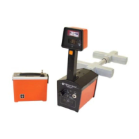
2-1 810 Line Tracer: Standard and Optional Equipment…………………..6
2-2 810 Transmitters: Controls and Indicators……………………………..9
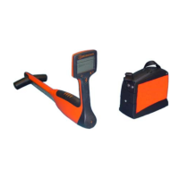
2-3 810 Receiver: Controls and Indicators…………………………………10
3-1 Position of Receiver for Checkout Procedure, Step 6…………………11
3-2 Checkout of Receiver Directional Meter………………………………12
3-3 Configuration for Testing the Conductive Attachment………………..13
3-4 Configuration for Testing the Metroclamp…………………………….14
4-1 Direct Connection…………………………………………………….. 15
4-2 Inductive Coupling with the Metroclamp…………………………….. 16
4-3 Signal Field Generated by Transmitter When in Inductive Use ………17
4-4 Position of Transmitter for Inductor Use………………………………17
4-5 Position of Receiver……………………………………………………18
4-6 810 Receiver Guidance System………………………………………..18
4-7 Determining the Depth of a Conductor………………………………...20
4-8 Position of Metroclamps When Using Two……………………….…. 21
5-1 Locating Conductors: Parallel Pattern…………………………………22
6-1 Ground on Either Side of Trace Area…………………………………..24
6-2 Position of Transmitter for Minimum Interference…………………..…25
6-3 Locating Service Laterals……………………………………………….25
7-1 Replacing the 810 Transmitter Batteries………………………………..26
 Loading...