18 6 BC 71 en
11 TYPE CODE
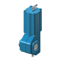
Pneumatic double-acting cylinder actuator, B1C
1. 2. 3. 4. 5. 6. 7. 8. 9. 10.
B1 C – S Q U 50/120 H E X
1. Product group
B1 Cylinder actuator with attachment dimensions acc. to ISO 5211
2. Series
C Double acting, pneumatic, protection class IP66.
3. Construction
- Standard construction without sign
H Manual hydraulic override
M Centre piece for manual operation (not possible, if 6. sign is U)
4. Cylinder and housing materials
-
Aluminium cylinder and EN 1561-GJL-200 housing, standard
materials, without sign. Except if sign 8. is arctic version "A"
then housing and piston always EN 1563-GJS-400-15.
S
Steel cylinder and EN 1561-GJL-200 housing and piston.
Except if sign 8. is arctic version "A" then housing and piston
always EN 1563-GJS-400-15. (Not available with size 6).
B
Aluminium cylinder and EN 1563-GJS-400-15 housing and
piston, (Not available with size 6).
When 8. sign is "A", without sign, standard material.
X
Steel cylinder and EN 1563-GJS-400-15 housing and piston,
(Not available with size 6).
5. Special construction
- Standard construction without sign
Q
Mechanical locking device for piston movement limit on
housing end. Locking with long screw to close position.
W
Mechanical locking device for piston movement limit on
cylinder end. Locking with long screw to open position.
QW
Mechanical locking device for piston movement limit on
housing and cylinder ends. Locking with long screw to close as
well as to open position.
Z
Actuator equipped with shock absorber on cylinder end, for
temperatures -20... +120 °C
N
Actuator equipped with shock absorber on housing end, for
temperatures -20... +120 °C
P
Actuator equipped with automatic latching device for closed
position. Design is made mainly for actuator locking device of
capping valve. No free motion.
T
Actuator equipped with manual latching device. Actuator can
be locked to open position allowing about 20 degrees' motion.
K Handwheel on cylinder end (sizes 9 to 25).
L Handwheel on housing end (sizes 9 to 25).
R
Handwheel both on cylinder end and housing end (sizes 9 to
25).
RK
Handwheel on cylinder end with wormgear (sizes 32 to 75).
Not used in 502, 602 and 752.
RL
Handwheel on housing end with wormgear (sizes 32 to 75).
Not used in 502, 602 and 752.
RR
Secondary handwheel with wormgear (sizes 32 to 75).
Not used in 502, 602 and 752.
Y Special
6.
INTERFACE FOR ADDITIONAL DEVICES
(positioner, limit switch)
U Interface according to VDI/VDE 3845, standard construction.
7. Actuator size
6/15 6/20 6/25 - 9/15 9/20 9/25 9/35 - 11/20 11/25 11/35 11/40 -
13/55 - 17/55 - 20/70 - 25/95 - 32/105 - 40/95 40/105 40/120 -
50/120 50/135 - 502/120 502/135 502/150 502/165 502/180
E.g. 50/120 = actuator size / shaft bore diameter.
Note special sizes (B1C 50 and 502 with oversized cylinder):
60 - max. supply pressure 8.5 bar
75 - max. supply pressure 5 bar
602 - max. supply pressure 8.5 bar
752 - max. supply pressure 5 bar
8.
Materials of seals and bearings
(all versions ATEX II 2 G c and ATEX II 3 G c)
- Standard construction without sign (-20° to +70 °C)
HL For temperatures -20... +120 °C and long-run option L
CL For temperatures -40... +70 °C, and long-run option L
C For temperatures -40... +70 °C
A
For temperatures -55... +70° C. Arctic service model. Not
available if 3. sign is "H" or 11. sign is "M". Size 6 not available.
F Oversized NPT connections: fast operation
F1 Larger oversized NPT connections: faster operation
L Long-run option
S Super long-run option (-20 to +70 ºC)
D
DU-bearings
- for sizes 32...502
Note: Not applicable with L, CL and HL options
Y Special
9. Screw material
-
Stainless steel (standard) for sizes 6-32.
Steel, zinc coated and passivated (standard) for sizes 40 and
bigger.
Steel, zinc coated and passivated for all sizes with steel
cylinder, sign 4 is S or X.
E
Stainless steel for sizes 40 and bigger with aluminium cylinder.
Stainless steel for all sizes with steel cylinder, sign 4 is S or X.
10. Non-standard operation range
- Standard, X=0, Y=90
X
Valve closed position is limited. When closed position is limited
to 30°, X = 30 (never fully closed).
Z
Valve open position is limited. When open position is limited to
70°, Z = 70 (never fully open).
XZ
Valve closed and open position are limited.
X = 30 (closed position is limited to 30°)
Z = 70 (open position is limited to 70°)
11. Special construction
6 Protection class IP66M
7 Protection class IP67/IP67M
G Oxygen service model
M K-mass fire protection
T Tropicalization
 Loading...


