6 BC 71 en 3
1 GENERAL
1.1 Scope of the manual
These instructions provide essential information for the use
of Metso B1C series actuators. For more details about
valves, positioners and accessories, refer to the separate
installation, operating and maintenance instructions of the
particular unit.
1.2 Structure and operation
The B1C series actuators are pneumatic cylinder actuators
designed for control and shut-off service.
The linkage bearings have material options. The robust
cast-iron housing efficiently protects the mechanism from
ambient dust and moisture.
The mounting face dimensions of the B1C actuator comply
with the ISO 5211 standard.
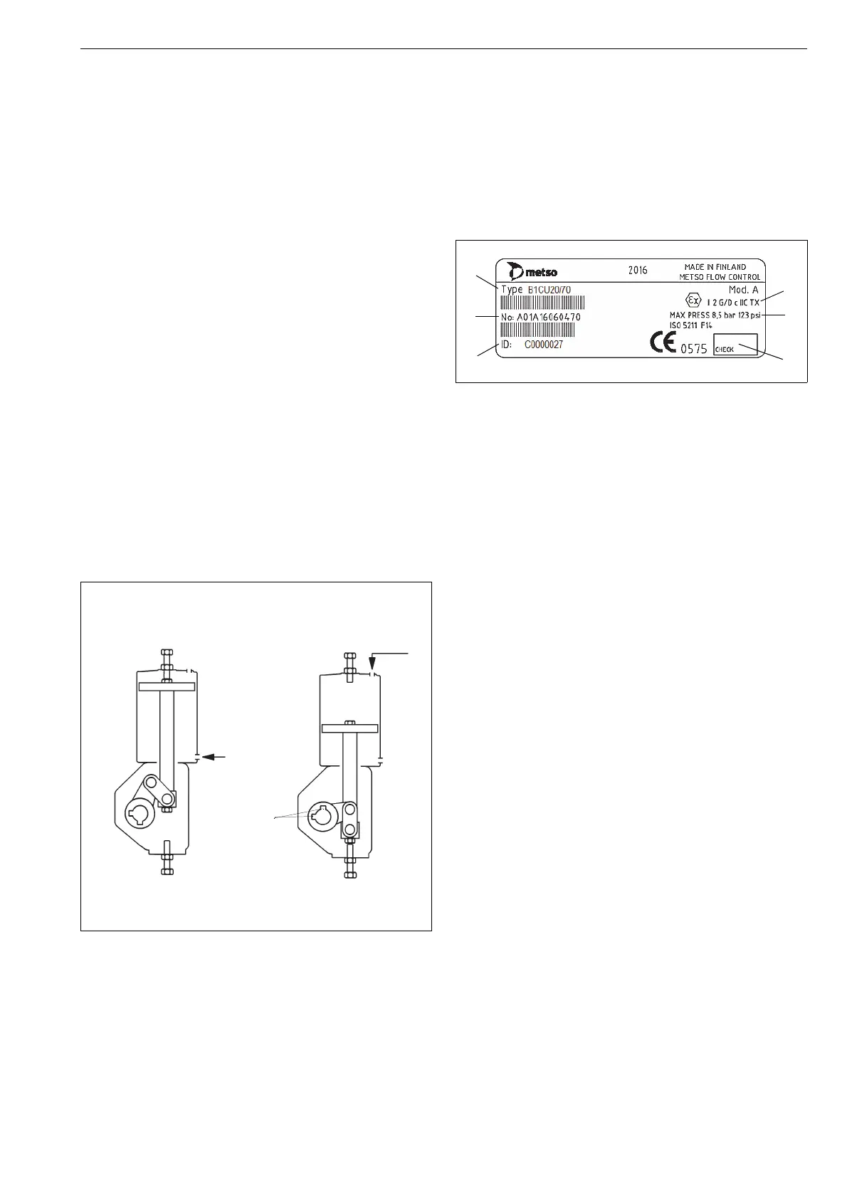
The linkage converts the linear motion of the piston into
rotation by the actuator shaft. The actuator generates maxi-
mum torque when for example a ball or butterfly valve is
closed, and the need for torque is greatest. Another peak is
achieved at 60-80°, when the need for torque on a butterfly
valve caused by the dynamic forces of for example pipe
flows reaches a maximum.
Screws are located in the upper end of the cylinder and in
the lower end of the housing to regulate the length of the
piston stroke and also the rotation angle of the actuator
shaft.
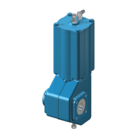
1.3 Actuator markings
The actuator is provided with an identification plate, see
Fig. 2. Identification plate markings are:
1. Type
2. Manufacturing site, date, successive no. (bar code)
3. SO number or ID number (bar code)
4. Checked by
5. Max. supply pressure
6. ATEX category and protection level
1.4 Specifications
Protection class: IP66, NEMA 4X
Ambient temperatures:
Standard design -20° to 70 °C / -4° to 160 °F
Low temperature design -40° to 70 °C / -40° to 160 °F
High temperature design -20° to +120 °C / -4° to 250 °F
Arctic temperature design -55° to +70 °C / -67° to 158 °F
Maximum supply pressure:
B1C 6...17, 60, 602 8.5 bar / 120 psi
B1C 20...50, 502 10 bar / 145 psi
B1C 75, 752 5 bar / 70 psi
Stroke volume, dm
3
/ in
3
B1C 6 0.33 / 20
B1C 9 0.60 / 37
B1C 11 1.10 / 67
B1C 13 2.30 / 140
B1C 17 4.30 / 262
B1C 20 5.40 / 329
B1C 25 10.50 / 640
B1C 32 21 / 1280
B1C 40 43 / 2620
B1C 50 84 / 5130
B1C 60 121 / 7380
B1C 75 189 / 11500
B1C 502 195 / 11900
B1C 602 282 / 17200
B1C752 441 / 26900
Fig. 1 Operating principle of the actuator
VALVE OPENVALVE CLOSED
opening
2 keyways
pressure
closing
pressure
Fig. 2 ID plate.
 Loading...


