Do you have a question about the Metso Neles L4 Series and is the answer not in the manual?
Provides essential information for users and refers to other manuals.
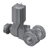
Describes the Neldisc L6 and L4 series double flanged and wafer type valves.
Explains markings on the valve body and identification plate for model recognition.
Lists specifications like pressure class, flange drillings, temperature, and flow direction.
Confirms valve meets European Directive 2014/68/EU for pressure equipment.
Details how to recycle valve parts and provides disposal instructions.
Lists critical safety warnings for valve operation, handling, and potential hazards.
Instructions for checking valve for damage, proper storage, and protection.
Remove port protectors and check valve for damage and cleanliness before installation.
Guides on pipeline flushing, valve installation positions, and trim considerations.
Instructions for installing the actuator, ensuring proper function and adequate space.
Guidance on flushing, startup, and initial operation of the valve.
Provides advice on preventative maintenance, inspection intervals, and using spare parts.
Step-by-step guide to safely remove the valve from the pipeline during maintenance.
Detailed procedure for replacing gland packing for specific valve series.
Procedure for replacing gland packing specifically for the L6F series valve.
Discusses causes of leakage and checks for disc position and actuator alignment.
Procedure for replacing the seat ring for specific valve series.
Procedure for replacing the seat ring specifically for the L6F series valve.
Steps for disassembling the valve to replace disc, shafts, and bearings.
Instructions for reassembling the valve after component replacement.
Steps to detach the B1 series actuator from the valve.
Instructions for detaching EC and EJ series actuators from the valve.
Precautions and notes before detaching or installing actuators on the valve.
Instructions for removing B1 series actuators from the valve.
Instructions for removing EC and EJ actuators from the valve.
Steps to install the B1 series actuator onto the valve.
Steps to install EC and EJ actuators onto the valve.
Refers to separate manuals for installing other actuator types.
General advice on adjusting stop screws for proper closed position torque.
Procedure for adjusting stop screws on B1C actuators for correct valve operation.
Procedure for adjusting stop screws on EC actuators for correct valve operation.
Procedure for adjusting stop screws on B1J (spring-to-close) actuators.
Procedure for adjusting stop screws on B1JA (spring-to-open) actuators.
Procedure for adjusting stop screws on M-series operators.
Refers to a separate leaflet for adjusting electric operators.
Lists recommended tools, specifically an extractor tool for actuator removal.
Details required information when ordering spare parts for the valve.
Provides an exploded view and detailed parts list for L6C and L6D valve models.
Provides an exploded view and detailed parts list for the L6F valve model.
Table of dimensions for manual gear operators in millimeters.
Table of dimensions for manual gear operators in inches.
Table of dimensions for B1C, B1J, B1JA pneumatic actuators in mm.
Table of dimensions for B1C, B1J, B1JA pneumatic actuators in inches.
Describes the S-disc construction for flow balancing trim on valve ports.
Details Neldisc series (L6, L4) and their design characteristics.
Lists pressure ratings for valve bodies, including ASME Class 150, 300, 600.
Explains seat design options like metal seat and pipe flange thread integration.
Describes construction, temperature limits, materials, and specific design options.
Lists the standard valve sizes available for different series and pressure classes.
Specifies available body material options like CF8M, WCB, and LCC.
Details disc material options, including CF8M, F316, and high-temperature alloys.
Specifies materials used for valve shafts and pins, such as 17-4PH and Nimonic.
Lists available seat material options, including Incoloy 825 and hard chrome plating.
Describes packing material options for glands, including graphite and PTFE.
Specifies flange drilling standards like ASME B16.5 and EN 1092-1.
Details flange facing requirements and standards for secure pipe connections.
| Brand | Metso |
|---|---|
| Model | Neles L4 Series |
| Category | Control Unit |
| Language | English |