Do you have a question about the Metso Neles ValvGuard VG9000F and is the answer not in the manual?
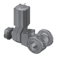
General information about the Neles ValvGuard VG9000F and its intended use.
Details the ValvGuard's microcontroller, spool valve, prestage unit, sensors, and interface.
Describes the identification plate and its markings for the ValvGuard.
Covers general, enclosure, environmental, pneumatic, and electronic specifications for the ValvGuard.
Provides guidance on how to recycle and dispose of ValvGuard components.
Outlines critical safety warnings and cautions for handling and maintenance of the ValvGuard.
General recommendations for mounting the ValvGuard, including IP66 class and orientation.
Instructions for mounting the ValvGuard on Metso actuators with VDI/VDE mounting faces.
Procedures for mounting the ValvGuard on linear actuators with IEC 60534 mounting faces.
Specific instructions for mounting and installing the VG9300 stainless steel version.
Details piping recommendations, air quality requirements, and supply pressure considerations.
Explains FOUNDATION fieldbus and 24 V DC safety signal connections and wiring.
How to view various measurements like valve position, pressure, and temperature via the LUI.
Describes the guided start-up procedure for initial configuration and calibration.
How to navigate the configuration menus using the LUI keypad.
Introduces configuration parameters and how to access them via the LUI.
Setting the actuator type (single/double acting) for optimal control performance.
Selecting valve type (rotary/linear) to compensate for linkage nonlinearity.
Configuring the valve's fail-safe action (Close/Open) during device failure.
Specifying external pneumatic instrumentation like boosters or quick exhaust valves.
Defining the actuator size based on type code or stroke volume for device control.
Selecting the spool valve type and size for proper device operation.
Setting the display language for the Local User Interface.
Procedures for calibrating the valve travel for accurate positioning.
Details the automatic calibration function and its successful/failed outcomes.
Overview of available tests, including Partial Stroke Test and Pneumatics Test.
Performing and understanding the Partial Stroke Test for valve diagnostics.
Executing the pneumatics test to check spool valve function without actuator movement.
Displays the status of mechanical limit switches connected to the ValvGuard.
Parameters for fine-tuning valve performance, including stroke time and profile.
Configuring valve opening/closing times and stroke profile shapes.
Setting the target size for manual partial stroke tests.
Defining the speed for manual partial stroke tests.
Enabling or disabling automatic partial stroke tests.
Information on special display modes like LUI locked, alarm/warning states, and event viewing.
How to lock the LUI to prevent unauthorized access or configuration.
Understanding alarm and warning indicators on the LUI display.
Accessing and viewing the most recent event message on the LUI.
How to enable or disable write protection for ValvGuard parameters.
Enabling simulation mode for testing valve position and diagnostics.
Step-by-step instructions for safely opening and closing the ValvGuard enclosure cover.
Information on the prestage unit, including removal and installation procedures.
Detailed steps for removing the prestage unit from the ValvGuard.
Instructions for removing the adapter plate associated with the prestage unit.
Steps for installing a new prestage unit and its adapter plate.
Information about the spool valve, its capacities, and maintenance advice.
Explanation of restricted and standard capacities for spool valve options.
Procedures for removing the spool valve assembly from the ValvGuard.
Steps for installing the spool valve assembly correctly.
Details regarding high capacity spool valves and their removal/installation.
Information on the communication circuit board, including removal and installation.
Steps for safely removing the communication circuit board.
Instructions for installing a new communication circuit board.
Introduction to ValvGuard models with limit switches and their applications.
Overview of ValvGuard variants with limit switches and their function.
Details the markings found on the identification plate for various limit switch types.
Technical data and electrical values for different limit switch types used with ValvGuard.
Technical details, electrical values, and ambient temperatures for the VG9_F/D_ model.
Technical details, electrical values, and ambient temperatures for the VG9_F/R_ model.
Technical details, electrical values, and ambient temperatures for the VG9_F/I_ model.
Technical details, electrical values, and ambient temperatures for the VG9_F/K_ model.
Technical details, electrical values, and ambient temperatures for the VG9_F/B_ model.
Tabulated electric data and ambient temperature ranges for various ValvGuard types.
Step-by-step instructions for installing limit switches onto an existing ValvGuard assembly.
Guidance on making electrical connections for limit switches, ensuring correct specifications.
How to adjust the limit switches using cam discs to set switching points.
Procedures for removing limit switches to access the ValvGuard assembly.
Internal circuit diagrams for the limit switch assembly.
Notes on the maintenance requirements for limit switches.
Visual exploded view and comprehensive parts list for the VG9000F model.
Exploded views and parts lists for VG9_F/D_, VG9_F/R_, VG9_F/I_, VG9_F/K_, VG9_F/B_ models.
Lists parts required for mounting the ValvGuard on Metso actuators with VDI/VDE faces.
Lists parts required for mounting the ValvGuard on Quadra-Powr® actuators.
Lists parts required for mounting the ValvGuard on linear actuators.
Provides detailed connection diagrams for FOUNDATION fieldbus and safety signal inputs.
Specific dimensional drawings for VG921_ models.
Specific dimensional drawings for VG923_ models.
| Brand | Metso |
|---|---|
| Model | Neles ValvGuard VG9000F |
| Category | Control Unit |
| Language | English |