Do you have a question about the Metso ND9200H and is the answer not in the manual?
Overview of primary functionalities and design attributes.
Highlights design robustness, environmental resistance, and durability.
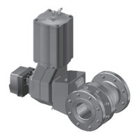
Introduction to the controller and its application with pneumatic actuators.
Detailed explanation of the microcontroller, measurements, and control logic.
Comprehensive data on performance, environmental, pneumatic, and electrical aspects.
Critical safety warnings and precautions for operation and handling.
General guidelines and recommendations for mounting the controller.
Specific instructions for mounting on EC and EJ type actuators.
Steps for mounting on Metso Automation actuators using VDI/VDE interface.
Procedure for mounting on actuators with IEC 60534 interface.
Guidelines for connecting pneumatic piping to the controller and actuator.
Details on wiring the controller for power and communication.
How to view various process measurements on the LUI display.
Step-by-step process for initial configuration and setup.
Navigating the menu structure for parameter adjustments.
Selecting between AUTO and MANUAL operating modes.
Detailed explanation of adjustable parameters for valve control.
Procedures for calibrating valve travel limits.
Enabling/disabling HART communication write protection.
Details on the prestage unit, including removal and installation.
Procedures for removing and installing the spool valve.
Instructions for removing and installing the communication board.
Guidance on replacing the controller circuit board.
Explains errors that trigger the fail-safe mode.
Lists and describes various alarm conditions detected by the controller.
Detailed list and descriptions of error messages.
Lists and explains warning messages generated by the controller.
Troubleshooting common mechanical and electrical issues affecting valve position.
Visual breakdown of the controller with itemized parts list.
Specific mounting hardware for EC05-14 actuators.
Specific mounting hardware for EJ05-14 actuators.
Mounting hardware for B1C/B1J 6-20 actuators.
| Brand | Metso |
|---|---|
| Model | ND9200H |
| Category | Control Unit |
| Language | English |