TRACTOR SIZE REQUIREMENTS
The spreader does not have brakes. Towing the
spreader must be done safely. The ASAE (American
Society of Agricultural Engineers) specifies that the
towing vehicle should weigh at least 2/3 as much as
the loaded implement to be reasonably safe towing at
speeds up to 20 mph. This (20 mph) is also the maxi-
mum recommended towing speed for the spreader.
The loaded weight of your spreader will naturally vary
with the moisture of the manure and you must consider
that for your conditions. The loaded weight capacities as
specified by the spreader manufacturer are as follows:
Tractor Towing Size Requirements
Use the following chart for calculating the minimum
tractor weight.
MODEL
(struck
level)
SPREADER EMPTY
WEIGHT + LOAD = GW
MINIMUM TRACTOR
WEIGHT UP TO 20
MPH
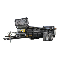
VB750
(478 ft
3
)
13,340+ _____ = _____ 2/3 of spreader gross
weight
Material Estimated Weight Per Cubic Foot
Material lbs / Cu. Ft.
Lime Sludge 110-115 LBS.
Dry Feedlot Manure 63-65 LBS.
Chicken Litter 63-65 LBS.
Cake Sludge 62-65 LBS.
Semi-Solid Manure 58-60 LBS.
Pen Packed Manure 30-35 LBS.
Liquid Manure 63-65 LBS.
SOURCE: ASAE
NOTICE! Heaped loads have significantly higher capaci-
ties resulting in increased weight and higher center of
gravity, requiring extra precaution during operation.
THEORY OF OPERATION
The spreader rear beaters are driven directly by the
tractor PTO.
The spreader rear end gate and the apron are hydrau-
lic driven. A single set of hydraulic hoses connected to
the tractor hydraulic system is used.
A directional valve is incorporated in the spreader hy-
draulic system which directs hydraulic flow to the rear
end gate only, when the gate is closed. With the gate
closed, applying the tractor hydraulics will open the
gate and as the gate opens, the directional valve is
acted upon by the gate arm and will direct hydraulic
flow to automatically start the apron drive motor.
When unloading is complete, the tractor hydraulic le-
ver is reversed to lower the gate and when the gate is
closed, the directional valve will stop hydraulic flow to
the apron motor. Furthermore, a check valve in the
apron motor circuit will prevent the apron drive motor
from running backwards. The check valve will also
prevent incorrect apron operation if the hydraulic
hoses are accidentally reversed at the tractor.
HYDRAULIC SYSTEM
General
There are two hydraulic systems available for this
spreader. Both systems are shipped for tractor closed
center hydraulics. If using a tractor with open center
hydraulics, instructions to convert the spreader system
to open center are given on page 13. Most late model
tractors are closed center systems. If in doubt, contact
your tractor dealer for information.
The standard
spreader hydraulic system does not in-
clude an on board flow control to regulate the apron
speed. Instead, the tractor must have an adjustable
flow control lever (turtle/rabbit icons) and this lever is
used to regulate the spreader apron speed.
If your tractor does not have adjustable flow control,
then your spreader must be equipped with the optional
on board flow control system. This system includes a
motorized flow control to regulate the spreader apron
speed. The motorized valve is adjusted by an electric
control box placed in the tractor cab and connected to
the tractor 12 VDC power source. See figure 5.
MODEL: VB750 Page 12