15
CHAPTER 3: AMPLIFICATION AND AUDIO
The 750-LFC’s driver is powered by a proprietary 2-channel,
open-loop, class D amplifier. The audio signal is processed
with correction filters for flat phase and frequency responses
and driver protection circuitry. Each channel has peak and
rms limiters that prevent driver over-excursion and regulate
voice coil temperatures.
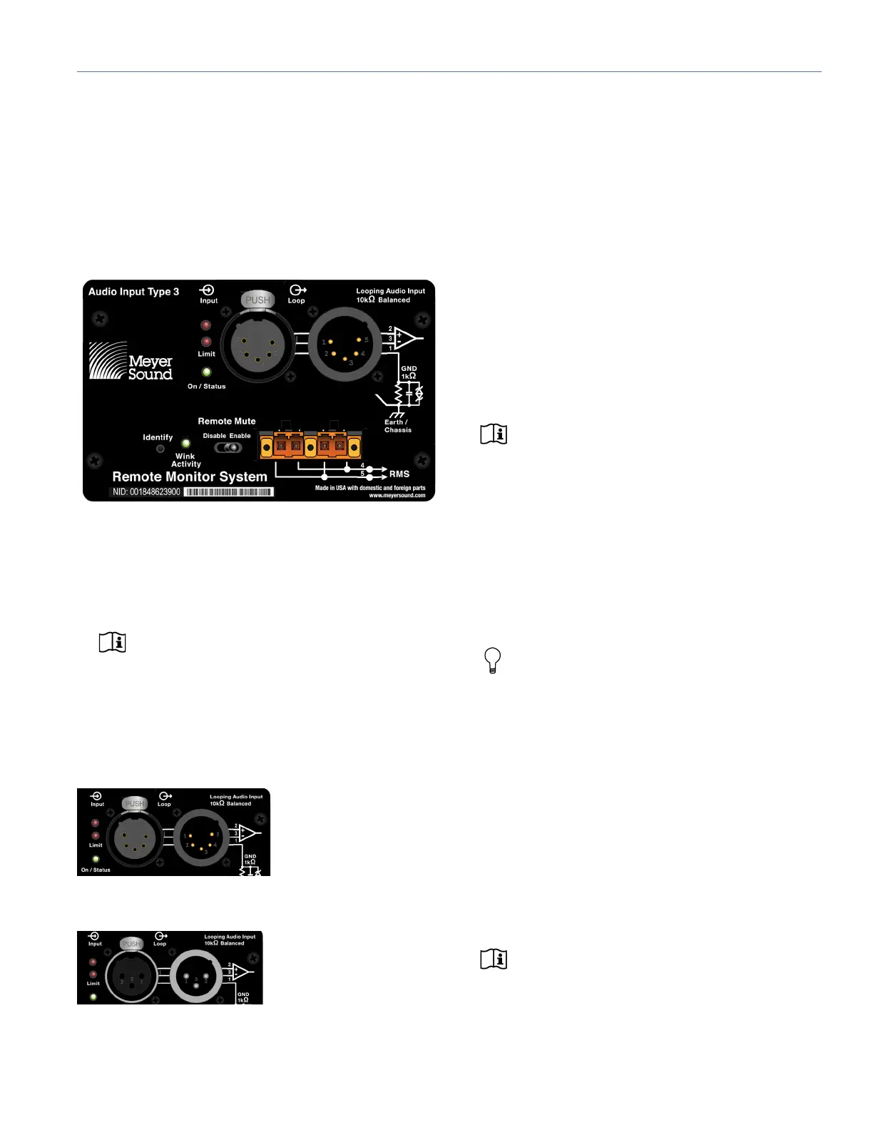
The 750-LFC user panel includes Input and Loop output con-
nectors for audio, Limit and On/Status LEDs, and RMS con-
nectors and controls (see Chapter 5, “Remote Monitoring
System (RMS) Option”).
NOTE: RMS is optional, so please specify this
feature when placing your order.
AUDIO CONNECTORS
The 750-LFC is available with XLR 3-pin or 5-pin connectors
for audio Input and audio Loop output. XLR 5-pin connec-
tors accommodate both balanced audio and RMS signals.
Audio Input (XLR 3-Pin or 5-Pin Female)
The XLR 3-pin or 5-pin female Input connector accepts bal-
anced audio signals with an input impedance of 10 kOhm.
The connector uses the following wiring scheme:
■ Pin 1 — 1 kOhm to chassis and earth ground (ESD
clamped)
■ Pin 2 — Signal (+)
■ Pin 3 — Signal (–)
■ Pin 4 — RMS (polarity insensitive)
■ Pin 5 — RMS (polarity insensitive)
■ Case — Earth (AC) ground and chassis
NOTE: Pins 4 and 5 (RMS) are included only
with XLR 5-pin connectors.
Pins 2 and 3 carry the input as a differential signal. Pin 1 is
connected to earth through a 1 kOhm, 1000 pF, 15 V
clamped network. This circuitry provides virtual ground lift
for audio frequencies while allowing unwanted signals to
bleed to ground. Make sure to use balanced XLR audio
cables with pins 1–3 connected on both ends. Telescopic
grounding is not recommended and shorting an input con-
nector pin to the case may cause a ground loop, resulting in
hum.
TIP: If unwanted noise or hiss is produced by the
loudspeaker, disconnect its input cable. If the
noise stops, there is most likely nothing wrong with the
loudspeaker. To locate the source of the noise, check
the audio cable, source audio, and AC power.
Audio Loop Output (XLR 3-Pin or 5-Pin Male)
The XLR 3-pin or 5-pin male Loop output connector allows
multiple loudspeakers to be looped from a single audio
source. The Loop output connector uses the same wiring
scheme as the Input connector (see “Audio Input (XLR 3-Pin
or 5-Pin Female)” on page 15). For applications that require
multiple 750-LFCs, connect the Loop output of the first
loudspeaker to the Input of the second loudspeaker, and so
forth.
NOTE: The Loop output connector is wired in
parallel to the Input connector and transmits
the unbuffered source signal even when the loud-
speaker is powered off.
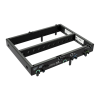
Figure 10: 750-LFC User Panel (XLR 5-pin version)
Figure 11: XLR 5-Pin Audio Connectors, Input and Loop Output
Figure 12: XLR 3-Pin Audio Connectors, Input and Loop Output
 Loading...