CHAPTER 4: QUICKFLY RIGGING
22
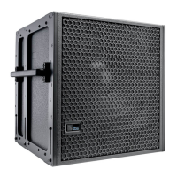
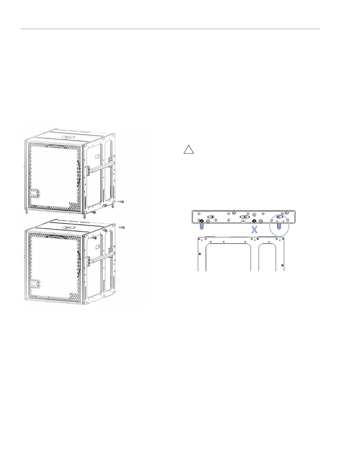
750-LFC GUIDEALINKS
When equipped with the MRK-750 rigging kit, the 750-LFC
includes six captive GuideALinks and six mating link slots
that link to adjacent units in flown and groundstacked arrays.
Located at the bottom of the cabinet, GuideALinks drop
down and into the link slots of the cabinet below it. GuideA-
Links extend and retract with knobs and are secured with two
quick-release pins: one each in the top and bottom cabinets.
GuideALinks accommodate reversed units for cardioid
arrays. The MRK-750 rigging kit includes eight 1/4 x 0.53-in
quick-release pins.
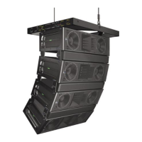
The 750-LFC’s GuideALinks accommodate both 750-LFCs
and LINAs without transition hardware. The front and rear
GuideALinks are used when flying the 750-LFC below the
MG-LINA/750 grid, or when flying it below another 750-LFC
(see Figure 18). The configuration of the 750-LFC’s GuideA-
Links, front and rear, determines its splay angle.
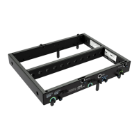
GLK-750 Grid Link Kit
The original MG-MINA grid (PN 40.207.101.01) includes only
the front and the middle links that allow flying MINAs or
LINAS from it. We recommend NOT using the middle link to
hang the 750-LFC because its load rating is about half of its
maximum capability.
We recommend using the updated version MG-
MINA/LINA/750 (PN 40.207.101.02) to hang 750-LFCs. You
can also update existing grids with the GLK-750-LFC grid
link upgrade kit (PN 40.207.301.01), which includes the two
rear links and installation hardware. Using the rear links,
instead of the middle, effectively increases the load rating
for the grid when attaching 750-LFCs.
CAUTION: Always use MAPP-XT to verify load
ratings. Under no circumstance should all six
links be used at the same time as this will not add any
load capability. In fact the load capacity will decrease
by about half of that provided by the rear links
because it cannot be determined which links are
actually under tension.
Figure 16: 750-LFCs with MRK-750 Rigging Kit, GuideALinks
Figure 17: 750-LFC rigging grid
 Loading...