MFJ-207 Instruction Manual HF 10-160M SWR Analyzer
SYSTEM CONTROLS AND INDICATORS
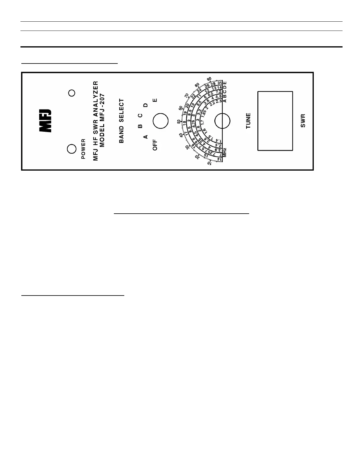
Front Panel Jacks and Controls
1 2 3 4
FIGURE 1: Front Panel Jacks and Controls
1. Power On LED: Instantly know if the MFJ-207 is on or off with this bright LED.
2. Band Select Switch: This 6 position switch turns the power on and selects any one of
five over lapping bands.
3. Tune Control: This variable capacitor instantly sweeps across the desired band to
find that SWR fast and easy.
4. SWR Meter: Direct readout of your SWR from 1:1 to Infinity.
Frequency Coverage of the Bands
NOTE: The frequency coverage may vary slightly from this chart and the label on the cover of the unit and is
for reference only. A frequency counter can be connected to the Freq. Out connector shown in Figure 2 to get a
more accurate reading of the frequency. As an alternative to a frequency counter you can Zero Beat the output
with an HF receiver. See Appendix A.
BAND A: 1.40 - 2.50 Mhz
BAND B: 2.40 - 4.50 Mhz
BAND C: 3.90 - 7.20 Mhz
BAND D: 7.00 - 14.00 Mhz
BAND E: 14.00 - 31.00 Mhz